

Resin Composition and Display Unit
a technology of composition and display unit, which is applied in the direction of synthetic resin layered products, instruments, transportation and packaging, etc., can solve the problems of reduced contrast and luminance of display units, difficulty in designing thinner display units, and other image defects, so as to reduce shrinkage stress and minimize the effect of stress on the image display part and the protective part, and high contrast display of images
- Summary
- Abstract
- Description
- Claims
- Application Information
AI Technical Summary
Benefits of technology
Problems solved by technology
Method used
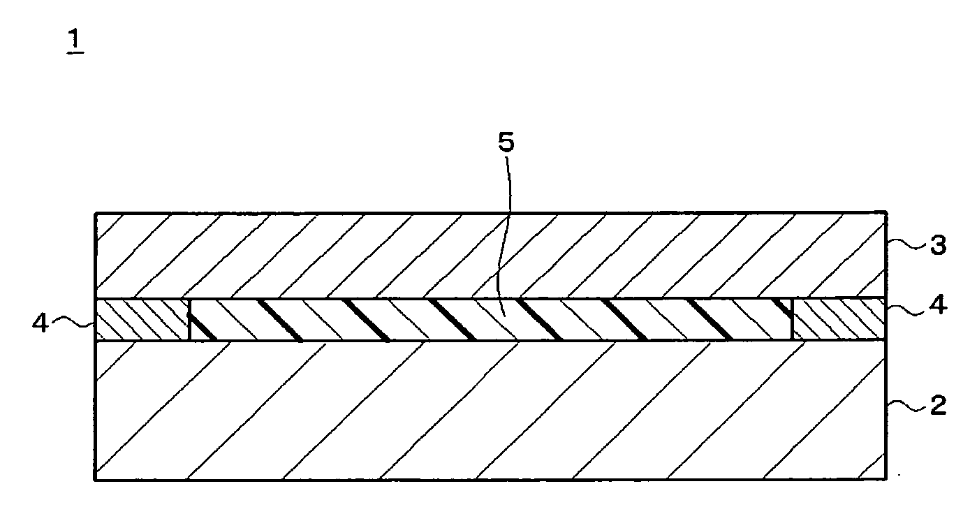
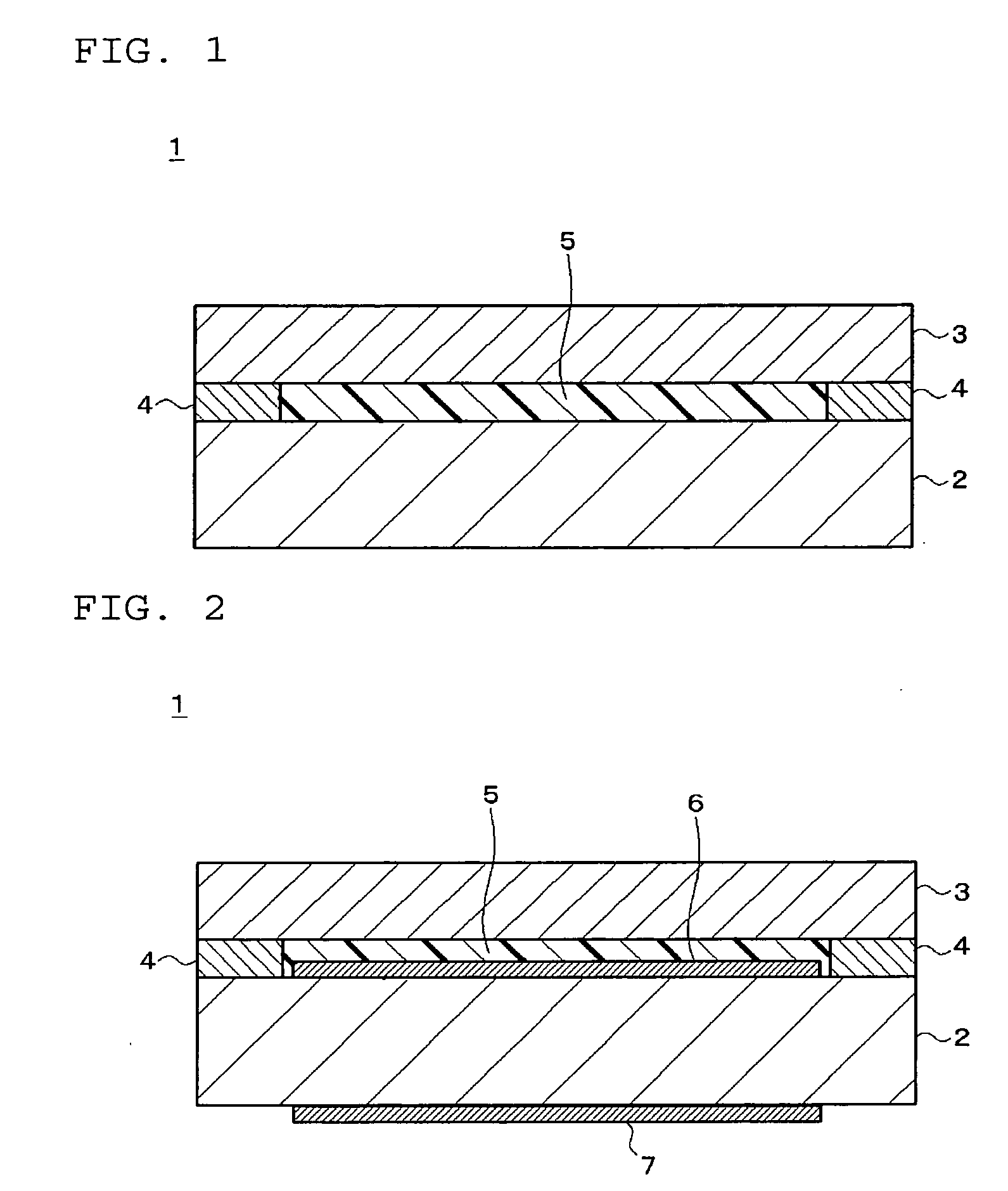
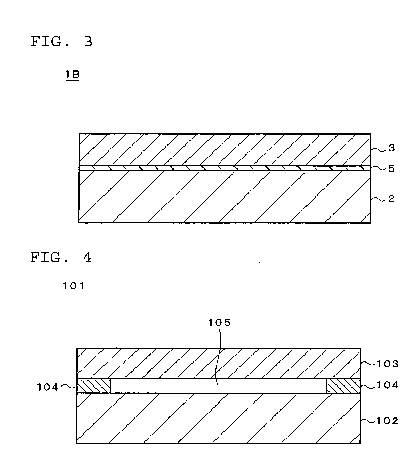
Image

Examples
example 1
[0057]The following components were kneaded together in a kneader to make a resin composition of Example 1: 50 parts by weight of polyurethane acrylate, 30 parts by weight of isobornyl acrylate, 3 parts by weight of a photopolymerization initiator and 1 part by weight of a photopolymerization initiator for visible-range.
example 2
[0058]The following components were kneaded together in a kneader to make a resin composition of Example 2: 70 parts by weight of an ester formed from a maleic anhydride adduct of a polyisoprene polymer and 2-hydroxyethyl methacrylate, 30 parts by weight of dicyclopentenyloxyethyl methacrylate, 10 parts by weight of 2-hydroxybutyl methacrylate, 30 parts by weight of a hydrogenated terpene resin, 140 parts by weight of a butadiene polymer, 4 parts by weight of a photopolymerization initiator and 0.5 parts by weight of a visible-range photopolymerization initiator.
example 3
[0059]The following components were kneaded together in a kneader to make a resin composition of Example 3: 100 parts by weight of an ester formed from a maleic anhydride adduct of a polyisoprene polymer and 2-hydroxyethyl methacrylate, 30 parts by weight of dicyclopentenyloxyethyl methacrylate, 10 parts by weight of 2-hydroxybutyl methacrylate, 30 parts by weight of a hydrogenated terpene resin, 210 parts by weight of a butadiene polymer, 7 parts by weight of a photopolymerization initiator and 1.5 parts by weight of a visible-range photopolymerization initiator.
PUM
| Property | Measurement | Unit |
|---|---|---|
| Temperature | aaaaa | aaaaa |
| Fraction | aaaaa | aaaaa |
| Fraction | aaaaa | aaaaa |
Abstract
Description
Claims
Application Information