Plant with Piping Mounted on Branch Pipe and Boiling Water Reactor Plant
a technology of boiling water reactor and piping, which is applied in the direction of nuclear reactors, greenhouse gas reduction, nuclear elements, etc., can solve the problems of acoustic resonance and damage to equipment in the bwr plant, and achieve the effect of suppressing the occurrence of acoustic resonance at the branch or the nozzle portion, and reducing the fluctuation pressure of the gas flowing in the piping
- Summary
- Abstract
- Description
- Claims
- Application Information
AI Technical Summary
Benefits of technology
Problems solved by technology
Method used
Image
Examples
first embodiment
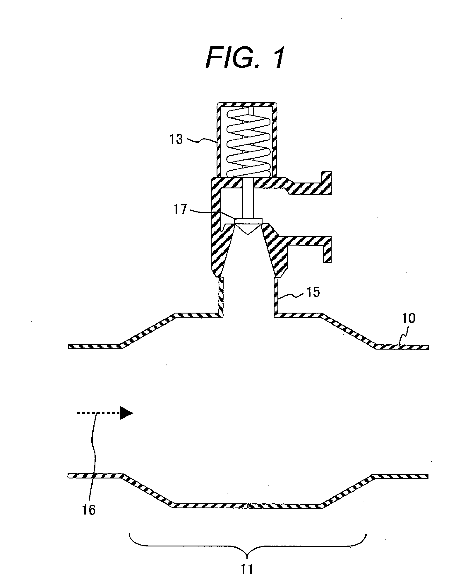
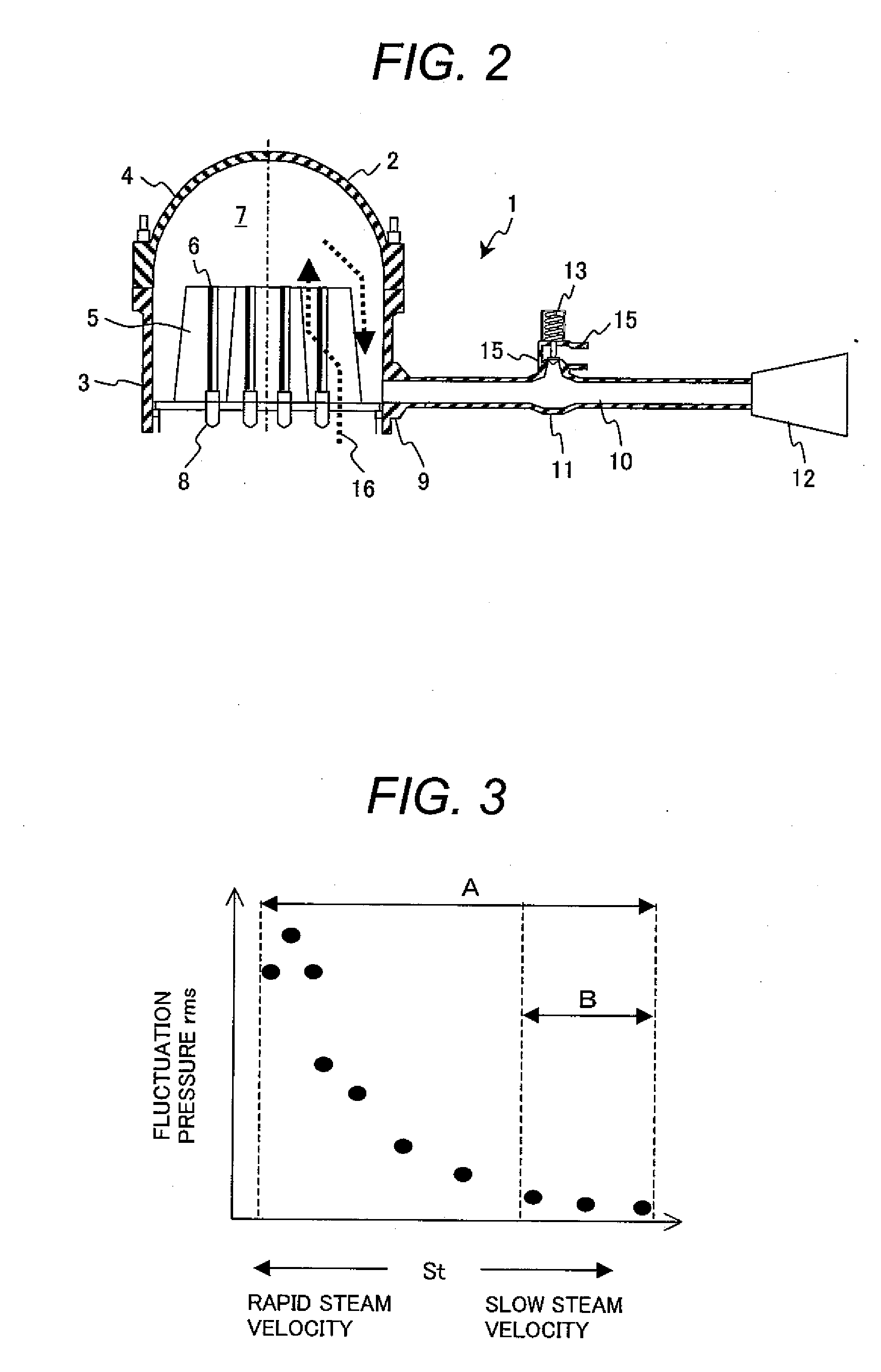
[0025]A plant with the piping mounted on branch pipe of a preferred embodiment of the present invention is described below by referring to FIG. 1 and FIG. 2. The plant with the piping mounted on branch pipe of the present embodiment is a BWR plant 1. The BWR plant 1 is provided with a nuclear reactor 2, a main steam pipe 10, a turbine 12, a condenser (not shown), and a feed water pipe (not shown).
[0026]The nuclear reactor 2 has a reactor pressure vessel 3 (hereinafter referred to as RPV) and a core placed in the RPV 3. Numbers of fuel assemblies (not shown) are loaded in the core. A removable cover 4 is attached to the RPV 3. In the RPV 3, a steam separator (not shown) is placed above the core, and a steam dryer 5 with corrugated plates 6 is placed above the steam separator. The main steam pipe 10 is connected to a nozzle 9 formed on the RPV 3, and is communicated with a steam dome 7 formed above the steam dryer 5 in the RPV 3. The turbine 12 is connected to the main steam pipe 10. ...
second embodiment
[0041]A plant with the piping mounted on branch pipe of another embodiment of the present invention is described below by referring to FIG. 4. The plant with the piping mounted on branch pipe of the present embodiment is a BWR plant 1A. The BWR plant 1A is comprised of a nuclear reactor 2, a main steam pipe 10A, a turbine 12, a condenser (not shown), and a feed water pipe (not shown). In the BWR plant 1A of the present embodiment, an enlarged passage portion is formed at a nozzle 9A formed on a RPV 3 and located upstream of a joint portion between the main steam pipe 10A and a vent pipe. In the present embodiment, the nozzle 9A is a part of the main steam pipe 10A. The BWR plant 1A has the same structure as that of the BWR plant 1 except that the enlarged passage portion is formed not at a branch portion 11 but at the nozzle 9A. The inner diameter of the nozzle 9A is larger than that of the main steam pipe 10A other than the nozzle 9A.
[0042]Since the passage sectional area of the no...
third embodiment
[0045]A plant with the piping mounted on branch pipe of another embodiment of the present invention is described below by referring to FIG. 5. The plant with the piping mounted on branch pipe of the present embodiment is a BWR plant 1B. The BWR plant 1B is, similarly to the BWR plant 1, comprised of a nuclear reactor 2, a main steam pipe 10, a turbine 12, a condenser (not shown), and a feed water pipe (not shown). In some BWR plants, a branch pipe 18 of which one end is sealed off is connected to the main steam pipe 10. In the BWR plant 1B of the present embodiment, the main steam pipe 10 is equipped with a branch pipe 18. An inner diameter of a joint portion between the main steam pipe 10 and the branch pipe 18, that is to say, a branch portion (an enlarged passage portion) 19 is larger than that of the main steam pipe 10 other than the branch portion 19. The passage sectional area of the branch portion 19 is larger than that of the main steam pipe 10 other than the branch portion ...
PUM
 Abstract
Description
Claims
Application Information
 - R&D
- Intellectual Property
- Life Sciences
- Materials
- Tech Scout
- Unparalleled Data Quality
- Higher Quality Content
- 60% Fewer Hallucinations
Browse by: Latest US Patents, China's latest patents, Technical Efficacy Thesaurus, Application Domain, Technology Topic, Popular Technical Reports.
© 2025 PatSnap. All rights reserved.Legal|Privacy policy|Modern Slavery Act Transparency Statement|Sitemap|About US| Contact US: help@patsnap.com


