Fuel cell system and control method therefor

a fuel cell and control method technology, applied in the direction of fuel cells, motive system fuel cells, reactant parameter control, etc., can solve the problems of limiting the output of the fuel cell, reducing the pressure in the closed space due to the consumption of fuel gas, and consuming fuel gas inside the closed space, so as to facilitate the judgment of the occurren

Active Publication Date: 2020-04-21
TOYOTA JIDOSHA KK
View PDF3 Cites 0 Cited by
  • Summary
  • Abstract
  • Description
  • Claims
  • Application Information

AI Technical Summary

Benefits of technology

[0011]With such an aspect, the power generation of the fuel cell is stopped while the judgment as to which of the on-off valve or the first pressure sensor has failed is being made. This causes fluctuations in the pressure of the fuel gas within the closed space to be suppressed when the on-off valve has not encountered the failure to close, and it is therefore possible to improve the degree of accuracy of the failure judgment for the first pressure sensor.
[0035]With such an aspect, it is possible to easily judge the occurrence of an abnormal pressure value detected by the first pressure sensor.

Problems solved by technology

When a certain failure occurs, the above-mentioned pressure sensors are likely to detect a pressure value which is much higher than the supply pressure of the hydrogen supplied to the fuel cell.
However, in the conventional configurations, whether such pressure increase results from a failure occurring in the pressure sensor or from other factors (e.g., an abnormal supply of hydrogen gas) has not been taken into consideration and room for improvement therefore still remains.
With such an aspect, since the fuel cell generates electric power while its output is limited, the fuel gas inside the closed space is consumed.
As a result, when the on-off valve has encountered a failure to close, pressure reduction in the closed space due to consumption of the fuel gas occurs in addition to the pressure reduction in the closed space due to the gas discharge mechanism.
The controller may cause, after closing the cutoff valve, the fuel cell to perform normal power generation; and the controller may start limiting the output of the fuel cell after a pressure value detected by the fourth pressure sensor has lowered below a threshold value.

Method used


Image

  • Fuel cell system and control method therefor
  • Fuel cell system and control method therefor
  • Fuel cell system and control method therefor

Examples


Embodiment Construction

[0039]Preferred embodiments of the present invention will be described below with reference to the attached drawings.

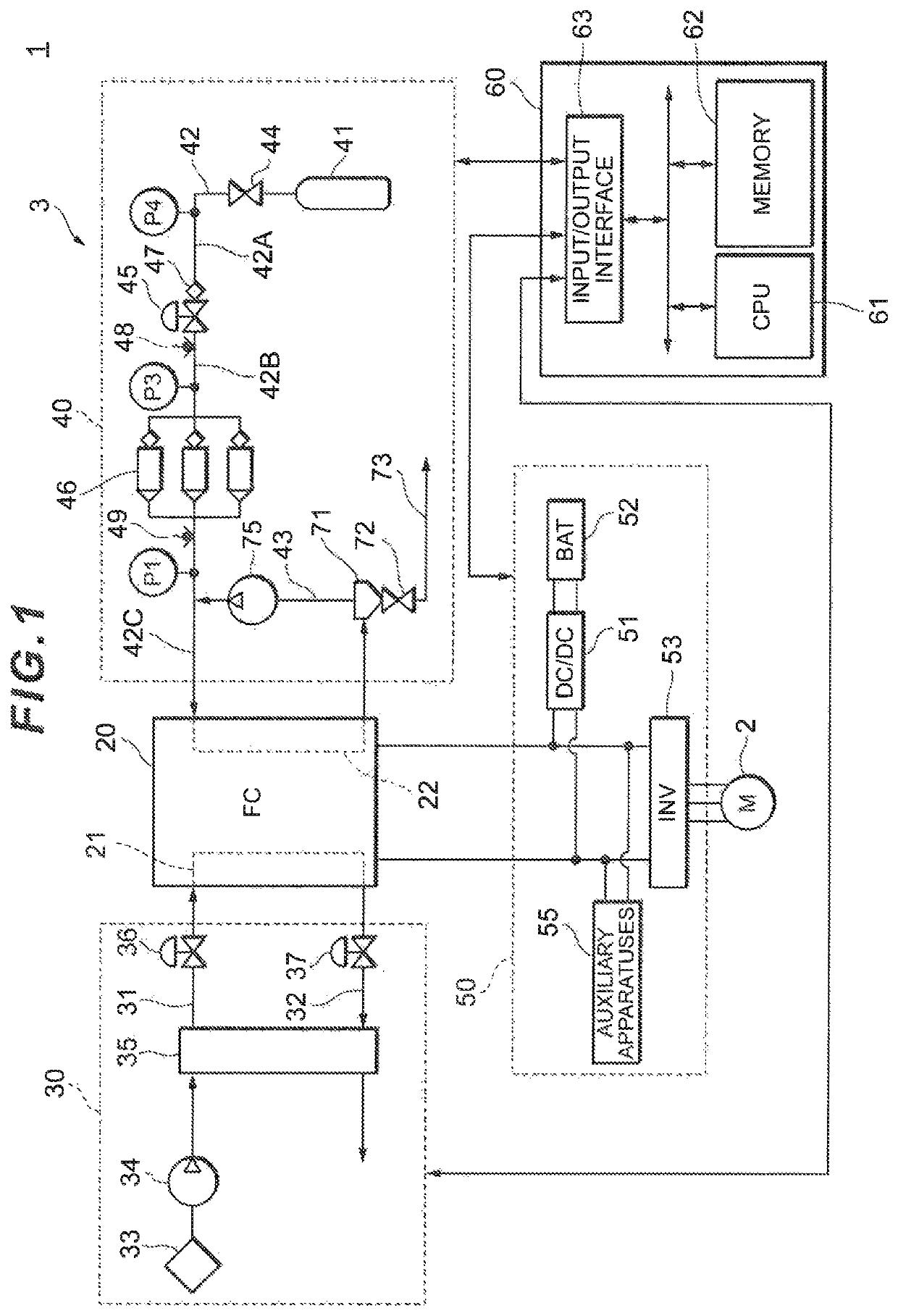
[0040]As shown in FIG. 1, a fuel cell vehicle 1 includes a traction motor 2 and a fuel cell system 3. The traction motor 2 may be, for example, a three-phase AC motor functioning as a power source for the fuel cell vehicle 1. The fuel cell system 3 may include a fuel cell 20 which generates electric power through electrochemical reaction between hydrogen gas and oxidant gas, an oxidant gas supply system 30 which supplies air as the oxidant gas to a cathode electrode of the fuel cell 20, a fuel gas supply system 40 which supplies hydrogen as the fuel gas to an anode electrode of the fuel cell 20, a power system 50 which controls charge and discharge of electric power, and a controller 60 which collectively controls the entire system. The fuel cell 20 may be a solid polyelectrolyte-type fuel cell stack formed by stacking a plurality of cells, for example, in series, and...


PUM

PropertyMeasurementUnit
pressureaaaaaaaaaa
pressureaaaaaaaaaa
pressureaaaaaaaaaa

Abstract

A controller closes a cutoff valve and a purge valve when a pressure value detected by a pressure sensor is an abnormal value. The controller then judges that an on-off valve has failed when the pressure value detected by the pressure sensor P1 has lowered, whereas the controller judges that the pressure sensor has failed when the pressure value detected by the pressure sensor has not lowered.

Description

CROSS-REFERENCES TO RELATED APPLICATIONS[0001]This application relates to and claims priority from Japanese Patent Application No. JP2017-49598, filed on Mar. 15, 2017, the entire disclosure of which is incorporated herein by reference.BACKGROUNDField[0002]The present invention relates to a fuel cell system.Description of Related Art[0003]JP2010-021127 A discloses a fuel cell system in which high-pressure hydrogen from a hydrogen tank is subjected to a pressure reduction using a pressure regulating valve and then supplied to a fuel cell. The supply pressure of the hydrogen supplied to the fuel cell is detected by a hydrogen pressure sensor arranged downstream from the pressure regulating valve. The hydrogen pressure sensor is driven by receiving a voltage from a constant-voltage regulator. In such fuel cell system, the output of the fuel cell is stopped when the constant-voltage regulator fails.[0004]In another known fuel cell system, the supply pressure of hydrogen supplied to a fu...

Claims


Application Information

Patent Timeline
Patent Type & Authority Patents(United States)
IPC IPC(8): H01M8/04H01M8/04089H01M8/04082H01M8/04664H01M8/0438H01M8/04746H01M8/04955H01M8/04223H01M8/04828
CPCH01M8/04097H01M8/04201H01M8/0438H01M8/04686H01M8/04089H01M8/04753H01M8/04104H01M8/04955H01M8/04231H01M8/04388H01M8/0494H01M8/0662H01M2250/20Y02E60/50
Inventor SAITO, HIROMU
Owner TOYOTA JIDOSHA KK
Why Eureka
Try Eureka