Measuring chromatic dispersion in an optical wavelength channel of an optical fiber link

a technology of optical fiber link and wavelength channel, which is applied in the direction of optical apparatus testing, transmission monitoring, instruments, etc., can solve the problems of affecting the ability of certain transmission systems to upgrade to transmit signals, and affecting the quality of transmitted signals

Active Publication Date: 2009-12-03
VIAVI SOLUTIONS INC
View PDF11 Cites 53 Cited by
  • Summary
  • Abstract
  • Description
  • Claims
  • Application Information

AI Technical Summary

Problems solved by technology

Excessive amounts of accumulated dispersion in high-speed optical communication systems can severely impair the quality of the transmitted signals.
For this reason, it is often unclear whether a certain transmission system can be upgraded to transmit signals at higher data rates, which usually are more sensitive to residual accumulated chromatic dispersion.
Obviously, the costs associated with such an approach are extensive, if not prohibitive.
Unfortunately, the entire transmission link has to be taken out of service in order to perform such measurements, because the two ends of the transmission link have to be connected to the measurement equipment.
Unfortunately, such measurements may not be possible in certain modern optical networks that employ fixed or re-configurable optical add-drop multiplexers (OADMs), because the various optical signals launched into a given span may be sent to different geographic locations or, in some cases, over substantially different routes to the same location.
To those skilled in the arts, it is well known that precise and simultaneous tuning of two laser sources and two narrowband optical filters requires substantial efforts and, hence, would be prohibitively expensive.

Method used


Image

  • Measuring chromatic dispersion in an optical wavelength channel of an optical fiber link
  • Measuring chromatic dispersion in an optical wavelength channel of an optical fiber link
  • Measuring chromatic dispersion in an optical wavelength channel of an optical fiber link

Examples


Embodiment Construction

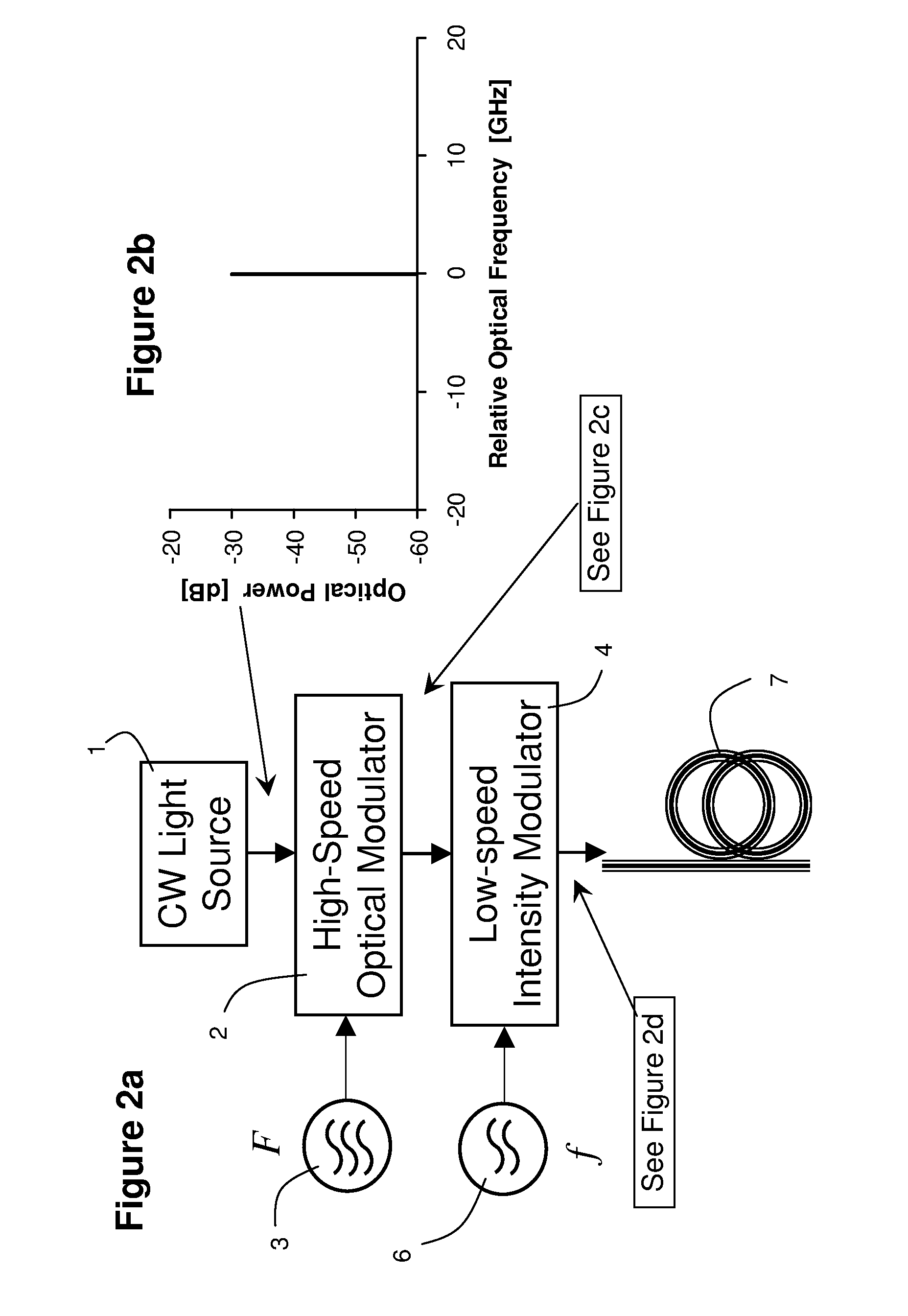
[0055]With reference to FIG. 2a, a front end apparatus of the present invention includes only one tunable laser source 1, which is tuned to a selected, e.g. the center, frequency of a wavelength channel to be measured, as graphically illustrated in FIG. 2b. Two modulated sideband test signals are generated from the single laser source 1 by means of a first electro-optic amplitude modulator 2, which is driven by a high-speed radio-frequency electrical signal with a frequency F generated by a high-speed RF signal generator 3. In a preferred implementation of the invention, the first amplitude modulator 2 is a chirp-free Mach-Zehnder interferometer, in which equal, but opposite, phase modulation is generated in the two arms of the interferometer, and the modulation frequency F is nominally 12.5 GHz. The modulation frequency F in principle can be as low as 1 MHz or as high as 100 GHz. In practical applications, it is usually preferred that F be as high as possible in order to obtain the...


PUM


Abstract

Two intensity modulated test signals are generated with precise frequency offset from a single laser source, and multiplexed into a combined test signal. The two modulated signals are demultiplexed at a receiver using a fixed periodic optical filter with complementary output ports. Group velocity dispersion / chromatic dispersion is measured over a large dynamic range, using pseudo-random intensity modulation and digital demodulation techniques.

Description

CROSS-REFERENCE TO RELATED APPLICATIONS[0001]The present invention claims priority from U.S. Patent Application No. 61 / 056,877 filed May 29, 2008, which is incorporated herein by reference for all purposes.TECHNICAL FIELD[0002]The present invention relates to measuring chromatic dispersion, and in particular to measuring total chromatic dispersion in a single optical wavelength channel of a multi-span optical communication system.BACKGROUND OF THE INVENTION[0003]Excessive amounts of accumulated dispersion in high-speed optical communication systems can severely impair the quality of the transmitted signals. The effect of accumulated dispersion is particularly important in fiberoptic communication systems that transmit signals over long spans of standard single-mode fibers, which may exhibit chromatic dispersion of up to 17 ps / nm / km. Therefore, the chromatic dispersion in the fiber link is often compensated for using dispersion-compensating modules that are interspersed with the fibe...

Claims


Application Information

Patent Timeline
Patent Type & Authority Applications(United States)
IPC IPC(8): H04B17/00H04B10/08
CPCG01M11/333H04B10/073G01M11/338G01M11/335
Inventor HEISMANN, FRED L.COLLINGS, BRANDON C.
Owner VIAVI SOLUTIONS INC
Why Eureka
Try Eureka