Variable output fluid pump system

Inactive Publication Date: 2009-12-03
METALDYNE LLC
View PDF57 Cites 2 Cited by
  • Summary
  • Abstract
  • Description
  • Claims
  • Application Information

AI Technical Summary

Benefits of technology

[0009]In accordance with another exemplary embodiment of the invention, a variable output pump system is provided, the pump system having a pressure-regulated slip drive for varying the output of at least one positive displacement pump. The pressure-regulated slip drive has at least one biasing member for providing a biasing force that tends to cause frictional engagement of at least a pair of engagement surfaces, and the pressure-regulated slip drive also has a fluid cavity in fluid communication with a fluid being pumped by the pump. The pressure of the fluid in the fluid cavity opposes the biasing force of the biasing member tending to engage the pair of engagement surfaces, thereby affecting the magnitude of the torque transmitted from one of the engagement surfaces to the other, thereby affecting the speed ratio between the engagement surfaces, and thus the output of the pump. The torque transmitted between engagement surfaces is preferably due to Coulomb friction during startup phases only, i.e. before fluid pressure is developed, thereafter transitioning to viscous oil film shearing between physically separated engagement surfaces of sufficient area and radius in order to avoid the wear inherent to Coulomb friction. The engagement surfaces are preferably formed with interactive lubricant passages that enable continually repeated flushing of the entirety of the contact areas of both members, for improved cooling and power dissipation capacity.
[0012]In still another exemplary embodiment, a method for varying the output of a positive displacement pump is provided, the method comprising: biasing at least one frictional engagement surface of a pressure-regulated slip drive towards frictional engagement with another frictional engagement surface with a biasing force in order to drive the pump. The biasing force is applied to a sealingly mobile load control member. Opposing the biasing force applied to the sealingly mobile load control member by fluid pressure in a fluid cavity disposed between a surface of the sealingly mobile load control member and a pressure containment member causes a reduction in the amount of the biasing towards frictional engagement of the at least two frictional engagement surfaces and thereby affects the output of the pump.

Problems solved by technology

The pressure of the fluid in the fluid cavity opposes the biasing force of the biasing member tending to engage the pair of engagement surfaces, thereby affecting the magnitude of the torque transmitted from one of the engagement surfaces to the other, thereby affecting the speed ratio between the engagement surfaces, and thus the output of the pump.

Method used


Image

  • Variable output fluid pump system
  • Variable output fluid pump system
  • Variable output fluid pump system

Examples


Embodiment Construction

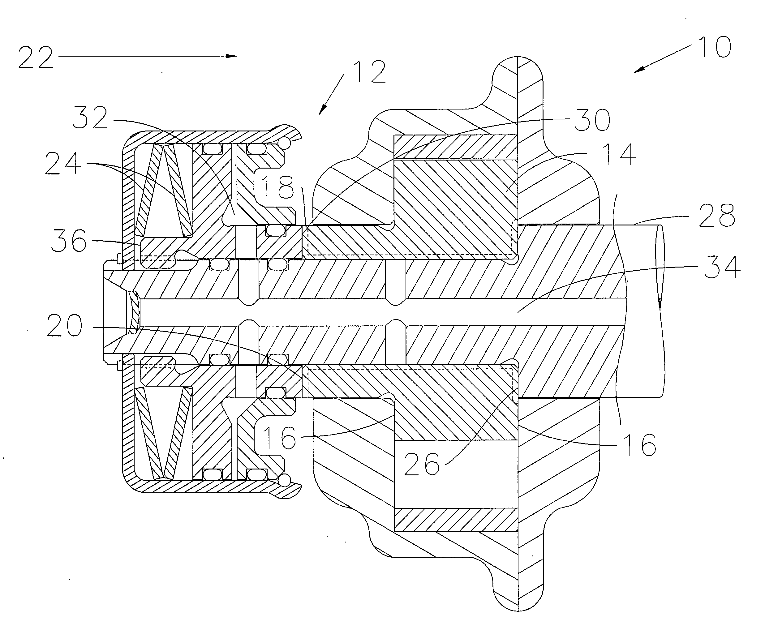
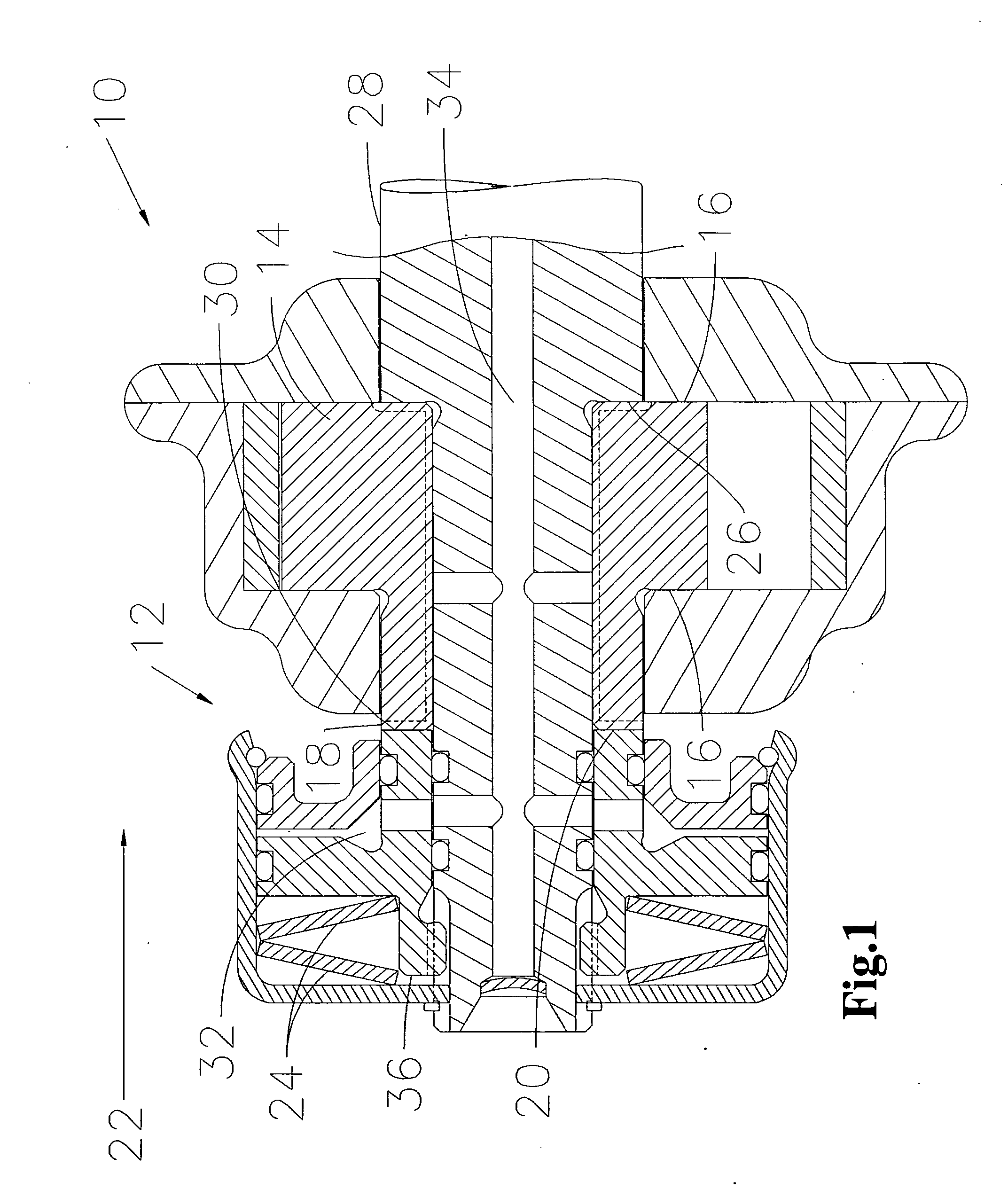
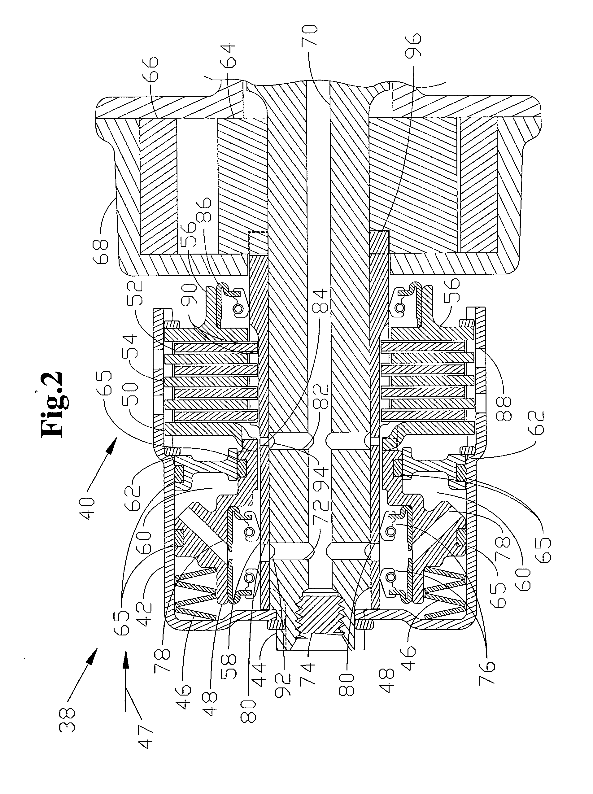
[0029]Exemplary embodiments of the present invention relate to a system comprising a low cost slip drive unit for the pressure-controlled driving of a positive displacement oil pump. The slip drive unit utilizes a predetermined axial clamping load that is applied to friction drive surfaces via a resilient biasing member (e.g., at least one Belleville disc spring or equivalents thereof). The axial clamping load is then reduced by hydraulic pressure that overcomes the biasing force of the biasing member to allow slippage of the friction drive surfaces, as needed, after a predetermined control pressure is attained, so as to limit pump speed to that which is necessary to maintain the predetermined pressure.

[0030]In one exemplary embodiment, the control pressure is taken from a remote branch of the lubrication network such as a balance shaft bearing, in order to assure that the desired pressure is available to all components downstream of the flow restrictions of, for example, those of t...


PUM


Abstract

A variable output pump system is provided, the pump system having a first positive displacement pump; a pump drive operably coupled to the first positive displacement pump, wherein the pump drive operates the first positive displacement pump to have a first output profile during a first operating range and a second output profile during a second operating range, the pump drive having a hydraulic release being configured to decrease the second output profile as a hydraulic pressure increases.

Description

CROSS REFERENCE TO RELATED APPLICATIONS[0001]This application claims the benefit of the following U.S. Provisional Applications Ser. No. 61 / 057,801 filed May 30, 2008; Ser. No. 61,059,069 filed Jun. 5, 2008; and Ser. No. 61 / 150,225 filed Feb. 5, 2009, the contents each of which are incorporated herein by reference thereto.BACKGROUND[0002]Exemplary embodiments of the present invention relate to fluid pumps, in particular a variable output pump system comprising a positive displacement pump and a variable speed ratio drive system.[0003]Positive displacement pumps are generally used in automotive and industrial applications due to their comparatively low overall cost and the packaging space requirements for such pumps. One example is an internal tip sealing gear type pump commonly known as a gerotor pump. These pumps (positive displacement gerotors and equivalents thereof) are configured to maintain oil pressure under certain conditions (e.g., high oil temperatures and engine idle rpm)...

Claims


Application Information

Patent Timeline
IPC IPC(8): F04B49/00
CPCF04C2/102F04C14/065F04C11/001
Inventor KILLION, DAVID L.
Owner METALDYNE LLC
Why Eureka
Try Eureka