
System, apparatus and method for biomedical wireless pressure sensing

Inactive Publication Date: 2009-12-03
CALIFORNIA INST OF TECH
View PDF15 Cites 98 Cited by
  • Summary
  • Abstract
  • Description
  • Claims
  • Application Information

AI Technical Summary

Benefits of technology

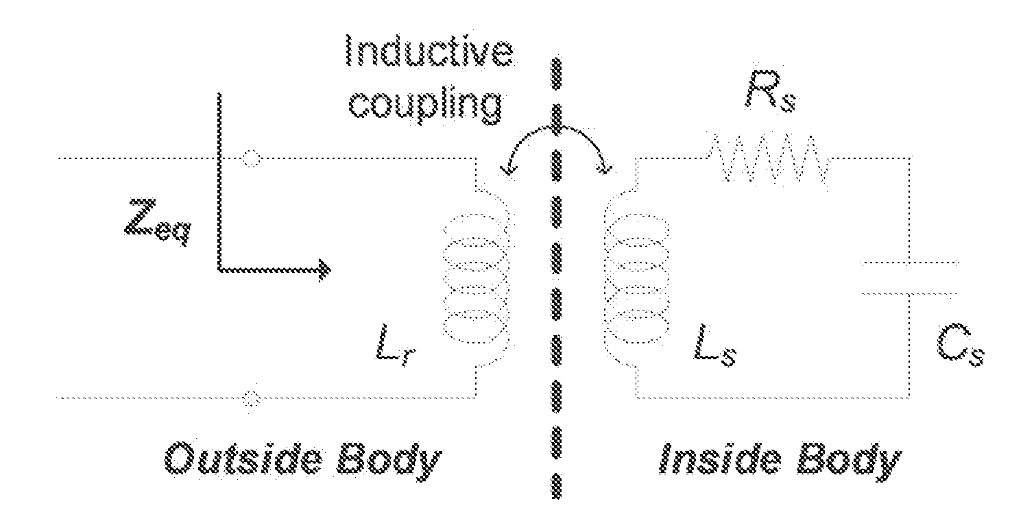
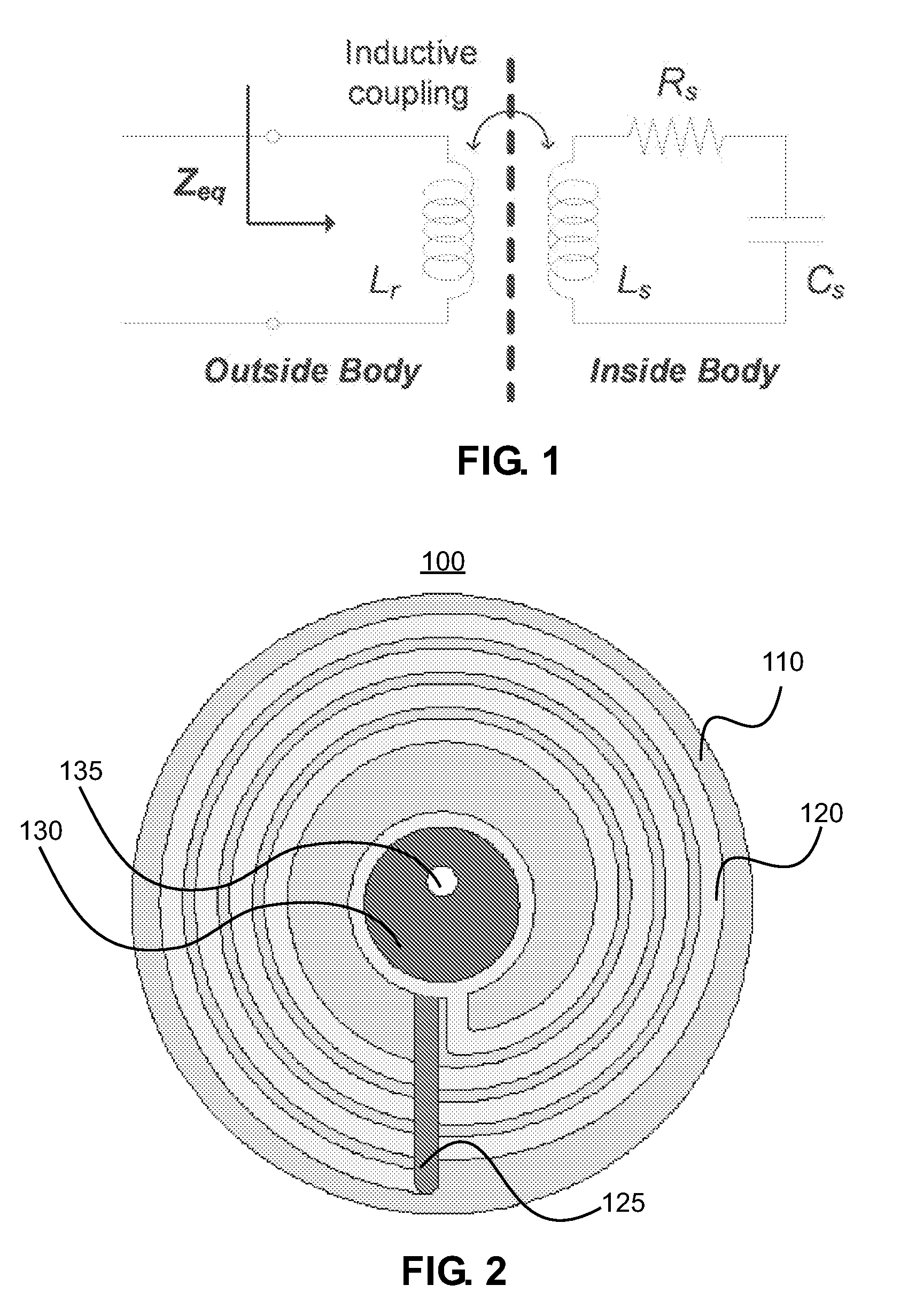
[0011]Embodiments of the present invention provide for wireless pressure sensing from implanted sensors which can be used, for example, for long-range continuous intraocular pressure (IOP) monitoring of glaucoma patients. One embodiment is an implantable parylene-based pressure sensor featuring an electrical LC-tank resonant circuit for passive wireless sensing without power consumption on the implanted site. The sensor is microfabricated with use of parylene C (poly-chloro-p-xylylene) to create a flexible coil substrate that can be folded for smaller physical form factor during implantation, while stretched back without damage for enhanced inductive sensor-reader coil coupling and the corresponding sensing signal. Additional embodiments feature designs to achieve suture-less minimally invasive surgery with less than 2 mm incisions. Another embodiment is a data-processing external readout method to support pressure measurement and analysis. Embodiments of the present invention can provide wireless pressure sensing with 1 mmHg resolution or better at distances of 2 cm distance or greater.

Problems solved by technology

Glaucoma is a debilitating eye disease that chronically damages the optic nerve and results in loss of vision for tens of millions of people worldwide.
However, both modalities have difficulties in providing reliable and repeatable measurements and, particularly, in deployment for regular (e.g., daily) tracking, which impedes prompt detection and appropriate treatment for IOP spikes from its diurnal fluctuations considered as a separate risk factor to optic nerve damage.
That is, for example, a sensing system that requires the coils of the external reader to be placed right against an eye for IOP measurements would be of limited usefulness due to the desire to take IOP measurements over an extended period of time.
Such systems show a decrease in reliability and resolution as the external reader coils move further from an implanted sensor.

Method used


Image

  • System, apparatus and method for biomedical wireless pressure sensing
  • System, apparatus and method for biomedical wireless pressure sensing
  • System, apparatus and method for biomedical wireless pressure sensing

Examples


Embodiment Construction

[0044]An embodiment of the present invention is a microfabricated implantable pressure sensor. This embodiment should measure pressure variations with a high sensitivity (1 mmHg) and high dynamic range (1-50 mmHg), which covers a broad spectrum of interest in biomedical applications in either acute or chronic study. The embodiment of the present invention comprising a microfabricated pressure sensor has a flexible / foldable inductor coil substrate. This flexible / foldable substrate allows minimally invasive device implantation without sutures when the implant is folded / rolled for a minimal required incision during surgery, while the flexible coil can be restored once in the implanted environment for electromagnetically data communication after surgery. Another embodiment of the present invention provides a data processing method featuring baseline / background subtraction and sample averaging / integration operations for realizing long distance (centimeter range) wireless sensing even wit...


PUM


Abstract

An implantable polymer-based pressure sensor featuring an electrical LC-tank resonant circuit for passive wireless sensing without power consumption on the implanted site. The sensor is microfabricated with parylene to create a flexible coil substrate that can be folded for smaller physical form factor during implantation, and can be stretched back without damage for enhanced inductive sensor-reader coil coupling. Data received from the sensor can be enhanced to provide improved pressure measurements at increased distances.

Description

CROSS-REFERENCE TO RELATED APPLICATIONS[0001]The present application is related to and claims the benefit of the following copending and commonly assigned U.S. Patent Application: U.S. Patent Application No. 61 / 130,635, titled “Biomedical wireless pressure sensing using microfabricated implantable flexible pressure sensor and data-processed external reading method,” filed on Jun. 2, 2008; the entire contents of which are incorporated herein by reference.BACKGROUND[0002]1. Field[0003]This disclosure relates to pressure sensors. More particularly, the present disclosure describes microfabricated implantable pressure sensors for use in biomedical applications and methods for such pressure sensing and the resulting systems. Such systems, sensors and methods may be used for monitoring intraocular pressure.[0004]2. Description of Related Art[0005]Pressure sensing is a powerful approach to study physiological conditions in biomedical applications and human healthcare. Glaucoma, hydrocephal...

Claims


Application Information

Patent Timeline
IPC IPC(8): A61B5/00
CPCA61B2560/063A61B5/031A61B3/16A61B5/0031A61B5/02014A61B2562/028A61B2562/0247
Inventor CHEN, PO-JUITAI, YU-CHONG
Owner CALIFORNIA INST OF TECH
Learn More