Illuminating Device and Plant Growth Apparatus Equipped With the Illuminating Device

a plant growth apparatus and illumination device technology, which is applied in the direction of saving energy measures, lighting and heating apparatus, and planar/plate-like light guides, etc., can solve the problems of plant death, increase the running cost of the plant growth apparatus, and temperature in the vessel, so as to improve the quality and yield of the grown plant products, improve the uniformity of luminance, and enhance the degree of plant growth

Inactive Publication Date: 2009-12-10
TOKUJU IND
View PDF5 Cites 26 Cited by
  • Summary
  • Abstract
  • Description
  • Claims
  • Application Information

AI Technical Summary

Benefits of technology

[0027]The present invention provides the following advantages.
[0028](a) The illuminating device according to the first aspect of the present invention comprises a light source 45 for irradiating a light in a specific direction, a reflection plate 41 disposed in a front side of an irradiating direction of the light source 45 for reflecting the light irradiated from the light source, and a transmissive and diffusive material member 42 disposed to face the reflection plate 41 for transmitting and diffusing the light from the light source 45 and the reflected light from the reflection plate 41, so that the light transmitted and diffused in the transmissive and diffusive material member 42 can be used as an illumination light.
[0029]Therefore, since the illuminating device according to the first aspect of the present invention is a so called indirect illuminating system in which the light irradiated from the light source 45 and the light reflected from the reflection plate 41 are transmitted and diffused in the transmissive and diffusive material member 42 and in which the light thus transmitted and diffused is used as an illumination light, the entire area to be illuminated can be illuminated as uniformly as possible. Such an indirect illuminating system is almost free of luminance spots which would be generated with, for example, a direct illuminating system and is able to improve uniformity of luminance. Therefore, when the illuminating device is used as an illuminating means for a plant growth apparatus, it is no longer necessary to adopt long distance illumination; namely the illuminating device allows for short distance illumination. As a consequence, uniformity of the degree of plant growth can be enhanced so that the quality and yield of the grown plant products are improved, thereby permitting a reduction of plant growth costs.
[0030]Additionally, the indirect illumination system permits most of the light from the light source 45 to irradiate on the plants. Thus, as compared with, for example, a direct illumination system in which a greater part of the light from the light source is scattered in directions other than the direction toward the target plants, the irradiation efficiency is high. Therefore, the number of the light sources 45 can be reduced so that the consumption of electric power for the illumination device can be suppressed in correspondence to the reduced number of the light sources 45, permitting a reduction of the running costs for the illuminating device.
[0031](b) In addition to the effects described in item (a) above, the second aspect of the present invention gives the following peculiar effect. That is, since the light source 45 of the illuminating device according to the first aspect of the present invention is specified in the second aspect of the present invention as a light source having directivity and since the irradiating direction thereof is so set as to conform to the specific direction, it is not necessary to provide means for changing the irradiation direction thereof. This can simplify the structure of the illuminating device, so that the initial cost for the illuminating device can be reduced.
[0032](c) In addition to the effects described in item (a) above, the third aspect of the present invention gives the following peculiar effect. That is, the light source 45 of the illuminating device according to the first aspect of the present invention is specified in the third aspect of the present invention as a light source having no directivity and is associated with a reflecting shade 44 so that the light irradiated from the light source is reflected by the reflecting shade in a direction conforming to the specific direction. By combining the light source 45 which is cheap itself with the reflecting shade 44 which is also cheap itself, it is possible to irradiate the light from the light source 45 toward a specific direction. Thus, as compared with a case in which a light source having directivity is used, for example, it is possible to reduce the cost of the illuminating device.

Problems solved by technology

There is also a fear that heat is accumulated in the culture vessels for growing clone seedlings, etc. thereby to increase the temperature in the vessels and to cause death of the plants.
(1) Use of a large number of the fluorescent lamps 105 requires a large consumption of electric power for the illumination and causes an increase of the running cost of the plant growth apparatus 100.
(2) When the number of fluorescent lamps 105 used is large, the ambient temperature of the plants 108 increases due to the heat generated from the illumination device 104, so that there is a fear that the growth of the plants 108 is adversely affected. In order to avoid such a fear, air conditioning of the closed space 107 must be conducted aggressively with an increased cost. This causes an increase of the running cost of the plant growth apparatus 100.
(3) The heat generated from the fluorescent lamps 104 causes a large temperature difference between upper and lower portions in the plant growth apparatus 100. As a result, a difference is created in the degree of growth between the plants 108 in the plant growing boxes 103 located in a high temperature upper side and the plants 108 in the plant growing boxes 103 located in a low temperature lower side. Thus, not only the uniformity of the plant growth but also the quality and yield of the grown plants are reduced.
(4) The illumination with straight fluorescent lamps 104 is so called a linear illumination system which is apt to cause luminance stripes or spots. Thus, among the plants 108 planted in the same plant growing box 103, the degree of growth varies with the planted positions. There is therefore a fear that not only the uniformity of the plant growth but also the quality and yield of the grown plants are reduced. To cope with this fear, a reflecting shade 106 is used. However, there is a limitation to such use of the reflecting shade. Satisfactory results are not obtainable.
(5) From the viewpoint of generation and radiation of heat and uniformity of the illumination, it is inevitable to adopt a long distance illumination and to provide a large vertical distance between the adjacent shelves 101. Therefore, the number of the stacked shelves 101 provided in a predetermined height must be reduced. As a result, the effective space utilization is reduced. Further, the initial cost and running cost of the plant growth apparatus 100 increase. At the same time, the productivity of the plant growth apparatus 100 is reduced.

Method used


Image

  • Illuminating Device and Plant Growth Apparatus Equipped With the Illuminating Device
  • Illuminating Device and Plant Growth Apparatus Equipped With the Illuminating Device
  • Illuminating Device and Plant Growth Apparatus Equipped With the Illuminating Device

Examples


first embodiment

A: First Embodiment

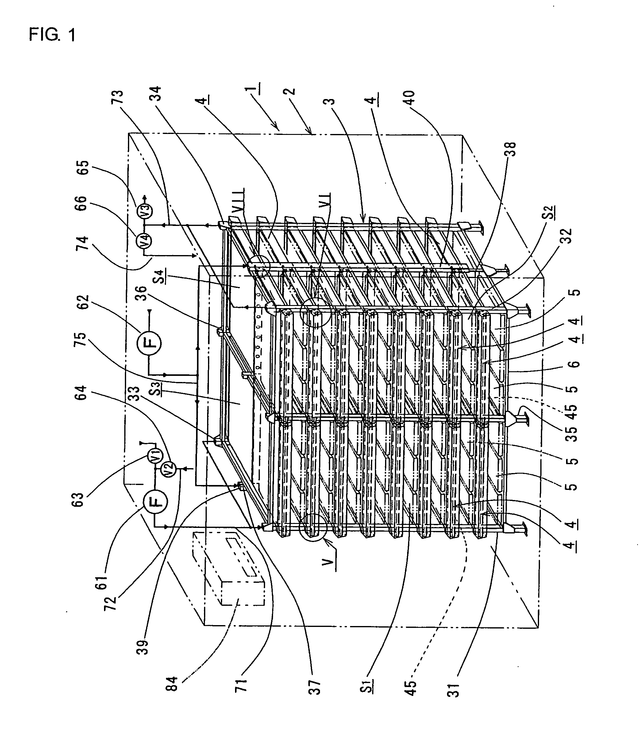
[0064]FIG. 1 depicts a plant growth apparatus 1 according to a first embodiment of the present invention. In the plant growth apparatus 1 a predetermined number of illuminating devices 4 according to the present invention are mounted in a growth rack 3 which will be described below. The growth rack 3 is disposed in a closed space defined in a growth housing 2.

Structure of Growth Rack 3:

[0065]The growth rack 3 comprises four supporting column 31 to 34 which stand at four corners of a rectangular area and which are integrally assembled into a cubic frame. In one side of the cubic frame, a fifth supporting column 35 is disposed at a center between the first and second supporting columns 31 and 32, while a sixth supporting column 36 is disposed at a center between the third and fourth supporting columns 33 and 34 in the opposite side. Further, a seventh supporting column 37 is disposed between the first supporting column 31 located in the one side and the third suppor...

second embodiment

B: Second Embodiment

[0133]FIG. 9 depicts a plant growth apparatus 1 according to a second embodiment of the present invention. The plant growth apparatus 1 has the same fundamental structure with that of the first embodiment and differs therefrom only in the construction of the plant growing box 5. Namely, in the plant growth apparatus 1 of the first embodiment, a top plate 46 of the illuminating device 4 is utilized as a shelf plate for supporting plant growing boxes 5 thereon. Thus, a predetermined number (three in the illustrated embodiment) of the plant growing boxes 5 in the form of relatively small but long trays are placed on the top plate 46. In the second embodiment, on the other hand, the plant growing box 5 is in the form of a tray having a dimension corresponding to the plan dimension of each of spaces S1 to S4 of a growth rack 3, as shown in FIG. 9. The plant growing box 5 is slid in and out on the top plate 46 of the illuminating device 4 in a drawer fashion. Thus, the...

third embodiment

C: Third Embodiment

[0137]FIG. 10 depicts a plant growth apparatus 1 of a third embodiment of the present invention. The plant growth apparatus 1 is a development of the first embodiment and has a growth rack 3 provided with eight spaces including front side four spaces S1 to S4 and rear side four spaces S5 to S8. Illuminating devices 4 are stacked in each of the spaces S1 to S8.

[0138]In each of the spaces S1 to S8 of the growth rack 3, illuminating devices 4 are stacked. A plant growing box 5 in the form of a laterally elongated planer tray encompassing the entire area of the spaces S1 to S8 is fixedly or detachably supported on the illuminating devices 4. The plant growing box 5 encompassing the entire area of the growth rack 3 is illuminated with the illuminating devices 4 positioned thereabove.

[0139]The above plant growing box 5 is used as a hydroponic culture vessel and always contains a predetermined amount of a culture liquid for hydroponic plant culture. A predetermined numbe...


PUM


Abstract

An illumination device includes a light source 45, a reflection plate 41 for reflecting the light irradiated from the light source 45, and a transmissive and diffusive member 42 for transmitting and diffusing the light from the light source 45 and the reflected light from the reflection plate 41, so that the light transmitted and diffused in the member 42 may be used for illumination. With this indirect illuminating system, an entire area can be uniformly illuminated with high efficiency, almost free of luminance spots. When the illuminating device is used in a plant growth apparatus, uniformity of plant growth is enhanced and the yield of the plants is improved. In addition, space for planting can be utilized to the maximum so that the number of grown plants significantly increases as compared with the conventional direct illumination system.

Description

BACKGROUND OF THE INVENTION[0001]1. Technical Field[0002]The present invention relates to an illuminating device suited for use in the growth of plants and to a plant growth apparatus using the illuminating device.[0003]As used herein the term “plant growth” is intended to include production of seedlings, namely culture of plug seedlings, grafted nursery plants and rooted cuttings in seedling growth trays and culture of clone seedlings in culture vessels, and product production, namely culture of product plants such as spinach and lettuce. The term “plant growth apparatus” is intended to include apparatuses for producing seedlings and apparatuses for producing plant products.[0004]2. Background Art[0005]In recent years, a plant growth apparatus 100 as shown in FIG. 11 has been increasingly used for the growth of plants (see Patent Document 1). This apparatus comprises a growth rack 102 having a plurality of vertically stacked shelves 101, a plant growing box 103 placed on each of th...

Claims


Application Information

Patent Timeline
Patent Type & Authority Applications(United States)
IPC IPC(8): A47F7/00A01G7/00F21V7/00F21V7/22F21V29/00
CPCA01G7/045G02B6/0011A01G9/26A01G9/249Y02A40/25Y02P60/14
Inventor TANAKA, MICHIOSAKATANI, EISHIROISOZAKI, MASAMI
Owner TOKUJU IND
Why Eureka
Try Eureka