Angular Resolution Radar Sensor

a radar sensor and angular resolution technology, applied in the field of radar sensors, can solve the problems of inability to contribute to the formation of secondary lobes of couplings between these signals, inability to separate inability to achieve the separation of signals in the spectrum, so as to simplify the construction of evaluation devices and improve the angular resolution. , the effect of simplifying the cost-effective construction

Inactive Publication Date: 2009-12-10
ROBERT BOSCH GMBH
View PDF7 Cites 21 Cited by
  • Summary
  • Abstract
  • Description
  • Claims
  • Application Information

AI Technical Summary

Benefits of technology

[0011]An objective of the present invention is to create a radar sensor that has an improved angular resolution capacity while also having a simple construction.
[0014]Another substantial advantage is that on the basis of the frequency offset it is possible to distinguish within the signal received from a single antenna element between the portion of the signal that was transmitted by this antenna element itself and the portions of the signal transmitted by other antenna elements. Thus, for an individual radar object, for example, that is located in the overlapping region of two radar lobes, two peaks are now obtained in the spectrum of each of the two associated channels, one of which represents the direct echo, i.e., the signal that was transmitted by the respective antenna element and was also received by it again, while the other peak represents the so-called cross echo that was transmitted by the other antenna element. The frequency difference between these two peaks corresponds to the frequency offset between the transmitted signals. If, in the radar sensor according to the present invention, one evaluates the complex amplitudes only at the apex of each peak, for example, one consequently obtains altogether four complex amplitudes from the two antenna elements involved, in contrast with only two complex amplitudes in the case of the conventional sensor. A substantially higher number of measured values is thus available for determining the azimuth angle, which markedly improves the angular resolution capacity. In particular, even when evaluating the signals of only two radar lobes, it is now possible to resolve two angularly offset objects that have the same distance and the same relative speed.
[0015]Overall, an improvement of the angular resolution capacity may thus be achieved without having to increase the aperture and thus the dimensions of the sensor and without a noticeable increase in the complexity of the sensor construction. On the transmitter side, only additional devices for producing the frequency offset between the transmitted signals are needed, and on the receiving side a somewhat greater bandwidth is needed so that the spectrum may be evaluated in a frequency range that includes the frequencies transmitted by multiple antenna elements.
[0016]The radar sensor is preferably constructed as an FMCW radar. The fact that the transmitting frequency is increased in at least one antenna element then yields the following additional advantage: As was explained above, the position of the signal generated by a radar object in the frequency spectrum is a function of the relative speed of the object and may thus at certain relative speeds also be shifted into the so-called DC range of the spectrum, i.e., into the frequency range surrounding the frequency zero, or even into the range of negative frequencies. It is not possible to detect or evaluate signal portions in the DC range using conventional FMCW radar sensors. In the complex intermediate frequency signal Z=|A|eift, positive and negative frequencies differ by the operational sign of frequency f. However, since in the conventional FMCW method in the end only the absolute value of the real component of the intermediate frequency signal is evaluated, it is not possible to distinguish between positive and negative frequencies, so that the measuring result may be falsified if significant signal portions are in the negative spectral range. In the FMCW radar according to the present invention, the intermediate frequency signal for each channel is formed by mixing the signal received from the respective antenna element with a base signal, the frequency of which is at most equal to the smallest of the transmitting frequencies supplied to the different antenna elements. At least for one of the channels, the signal in the spectrum is therefore shifted by the frequency offset to positive frequencies such that the entire signal or at least a greater portion of it now lies in the positive frequency range capable of evaluation.
[0019]Because for improving the angular resolution it is sufficient that the transmission signals of all antenna elements are decoupled and that the cross echo is evaluated in each case for one of the antenna elements involved in this cross echo, a simplified cost-effective construction may be achieved in that for some channels, e.g., those that correspond to the outermost left and outermost right radar lobe, the intermediate frequency signal is formed as usual by mixing the received signal with the signal actually transmitted by the respective antenna element such that the frequency of the intermediate frequency signal is not raised. Although it is then not possible to detect cross echoes in these channels, the advantage is a simplified construction of the evaluation device. In particular, narrower-band and thus more cost-effective analog / digital converters may be used.

Problems solved by technology

Alternatively, however, the antenna elements may be so-called phased arrays made up of multiple sub-elements, which are supplied with transmission signals having such a phase relationship that the desired directional characteristic results by interference.
Now, if, for example, two objects differ in their azimuth angle, but have the same distance and the same relative speed, then their signals can no longer be separated in the spectrum such that the radar sensor is unable to resolve the different azimuth angles of the two objects.
Another effect that impairs the angular resolution capacity of the known radar sensor results from the fact that the individual antenna elements do not generate sharply bundled beams, but rather relatively widely fanned radar lobes, due to diffraction and interference effects.
Because of the frequency offset, the signals transmitted by the different antenna elements are decoupled from one another such that couplings between these signals are no longer able to contribute to the formation of secondary lobes.
It is not possible to detect or evaluate signal portions in the DC range using conventional FMCW radar sensors.
In the complex intermediate frequency signal Z=|A|eift, positive and negative frequencies differ by the operational sign of frequency f. However, since in the conventional FMCW method in the end only the absolute value of the real component of the intermediate frequency signal is evaluated, it is not possible to distinguish between positive and negative frequencies, so that the measuring result may be falsified if significant signal portions are in the negative spectral range.

Method used


Image

  • Angular Resolution Radar Sensor
  • Angular Resolution Radar Sensor
  • Angular Resolution Radar Sensor

Examples


Embodiment Construction

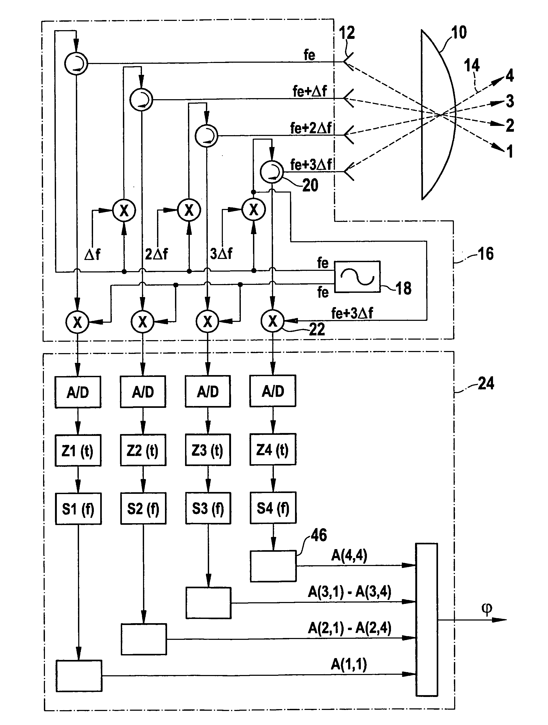
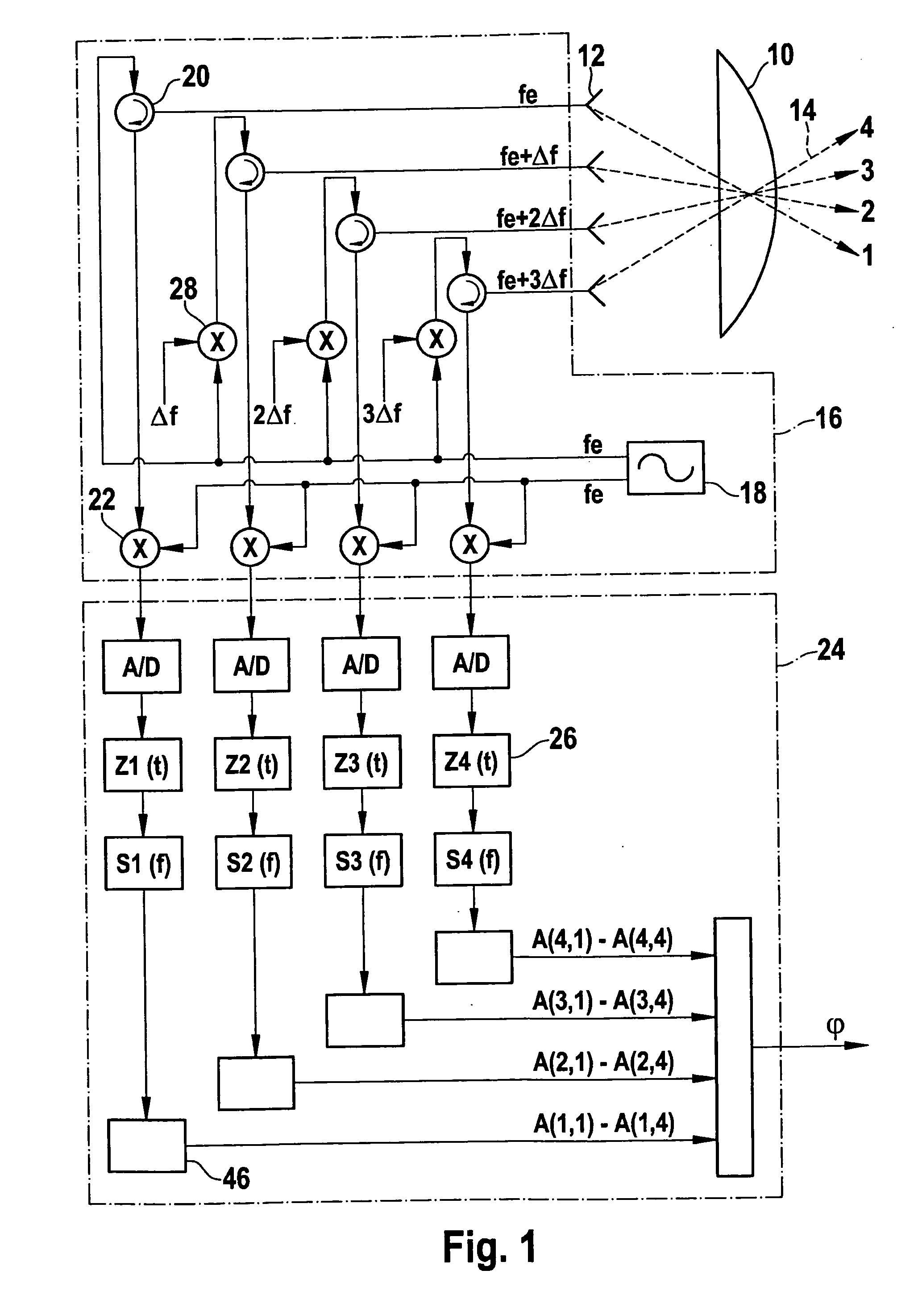
[0031]FIG. 1 shows the basic construction of an angular resolution FMCW radar sensor having a lens 10, in the focal plane of which four antenna elements 12, e.g., patch antennas, are situated at a varying offset with respect to the optical axis of lens 10. Antenna elements 12 thus produce radar beams 14, which are bundled by lens 10 and then emitted in different directions. Each antenna element 12 is part of one channel of the radar sensor. For differentiation, the channels are numbered consecutively by numerals 1-4 on the associated radar beams 14.

[0032]A transmitting and receiving element 16 has a local oscillator 18 (VCO; voltage controlled oscillator), which generates a microwave signal having a base frequency fe of 76 GHz for example. For channel 1, this base frequency signal is fed via a circulator 20 directly into associated antenna element 12. The signal received from this antenna element is separated from the fed-in signal by circulator 20 and is then mixed in a mixer 22 wi...


PUM


Abstract

A radar sensor having multiple antenna elements for transmitting and receiving radar signals, an associated transmitting and receiving element and an evaluation device for determining the azimuth angle of located objects on the basis of a relationship between the signals received from different antenna elements, wherein the transmitting and receiving element is designed to supply to the antenna elements transmission signals in parallel, the frequencies of which are offset with respect to one another, and the evaluation device is designed to distinguish between signals that were transmitted by different antenna elements on the basis of the frequency offset.

Description

FIELD OF THE INVENTION[0001]The present invention relates to a radar sensor having multiple antenna elements for transmitting and receiving radar signals, an associated transmitting and receiving element and an evaluation device for determining the azimuth angle of located objects on the basis of a relationship between the signals received from different antenna elements.BACKGROUND INFORMATION[0002]Antenna elements may be individual antennas or patches, for example, which are offset with respect to the optical axis of a common radar lens. The directional characteristic of each antenna element, specifically the direction in the greatest radiation intensity or the greatest sensitivity, is then given by the offset of the respective element with respect to the optical axis. Alternatively, however, the antenna elements may be so-called phased arrays made up of multiple sub-elements, which are supplied with transmission signals having such a phase relationship that the desired directional...

Claims


Application Information

Patent Timeline
Patent Type & Authority Applications(United States)
IPC IPC(8): G01S13/48G01S13/931
CPCG01S7/352G01S13/345G01S2013/9325G01S2007/356G01S2013/9321G01S13/931G01S7/356
Inventor HILSEBECHER, JOERGSTEFFENS, WOLF
Owner ROBERT BOSCH GMBH
Why Eureka
Try Eureka