
Wireless Terminal Apparatus and Wireless Base Station Apparatus

a technology of wireless base station and terminal station, which is applied in the direction of multiplex communication, wireless commuication services, orthogonal multiplex, etc., can solve the problem of small number of terminal stations to which the code can be assigned

Active Publication Date: 2009-12-10
TOYOTA JIDOSHA KK
View PDF1 Cites 36 Cited by
  • Summary
  • Abstract
  • Description
  • Claims
  • Application Information

AI Technical Summary

Benefits of technology

[0008]The present invention was conceived in order to solve the above-described problem and has an object to provide both a wireless terminal apparatus and wireless base station apparatus that can, in an operation of encoding the control signals of the upstream link transmitted from the multiple terminal stations while encoding with regard to each of the terminal stations, increase a number of the terminal stations to which different codes are respectively assigned.
[0014]In accordance with the above-described first, second and fourth aspects, in an operation of encoding the control signals of the upstream link transmitted from the multiple terminal stations while encoding with regard to each of the terminal stations, it is possible to increase a number of the terminal stations to which different codes are respectively assigned. In addition, in accordance with the above-described third aspect, it is possible to use CAZAC that is generally known.

Problems solved by technology

However, the above-described conventional technique assigns CAZAC code of the different phase shift amount to each of the terminals, but has a problem in which a number of the terminal stations to which the code can be assigned is small.

Method used


Image

  • Wireless Terminal Apparatus and Wireless Base Station Apparatus
  • Wireless Terminal Apparatus and Wireless Base Station Apparatus
  • Wireless Terminal Apparatus and Wireless Base Station Apparatus

Examples


example 1

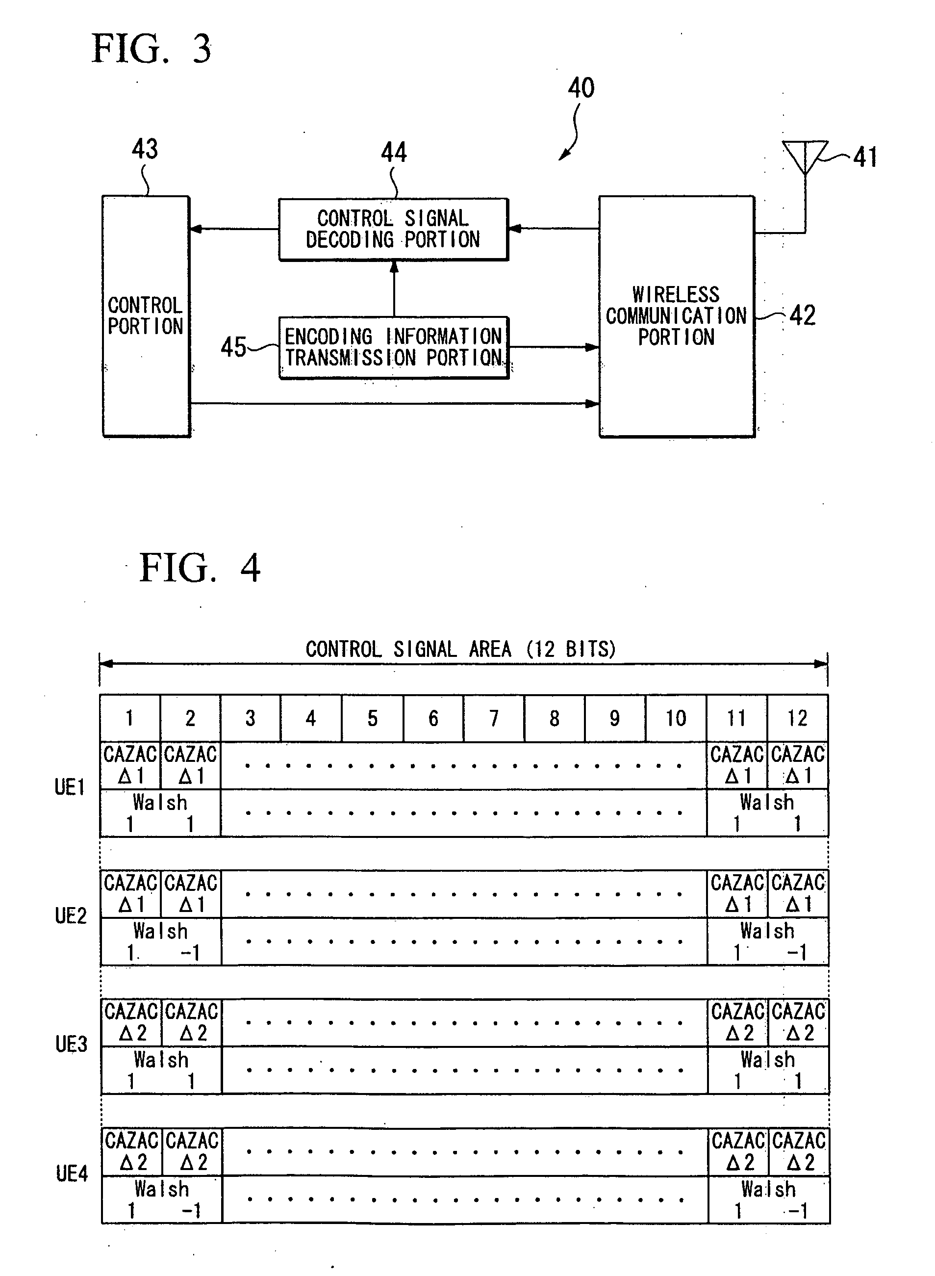
[0050]FIG. 4 is a drawing for explaining Example 1 in which the first code and the second code of this example are used. In the Example 1, a pair of Walsh codes of two dimensions “(1,1) and (1,−1)” are used. In FIG. 4, a control signal area has a 12 bit length, and the encoding operation is conducted on data stored in this 12 bit area. In an example shown in FIG. 4, each of four terminal stations 1 (“UE1”, “UE2”, “UE3” and “UE4”) transmits a control signal of an uplink to the base station 40 which is a single base station.

[0051]As shown in FIG. 4, both “UE1” and “UE2” conducts an encoding operation on the control information by using CAZAC codes obtained by a phase-shifting of amount of Δ1. In addition, “UE1” conducts the encoding operation on the control information by using Walsh code of (1, 1), and “UE2” conducts the encoding operation on the control information by using Walsh code of (1, −1). In accordance with such a manner, even when both of CAZAC codes have the same amount of...

example 2

[0054]FIG. 5 is a drawing for explaining Example 2 in which a first code and a second code are used. In the Example 2, Walsh codes of four dimensions “(1, 1, 1, 1), (1, −1, 1, −1), (1, 1, −1, −1), (1, −1, −1, 1)” are used. In an example shown in FIG. 5, in the similar manner as shown in FIG. 4, an encoding operation is conducted on a control signal area of 12 bits. In the similar manner as shown in FIG. 4, each of four terminal stations 1 (“UE1”, “UE2”, “UE3” and “UE4”) transmits a control signal of an uplink to the base station 40 which is a single base station.

[0055]As shown in FIG. 5, by using the CZAC codes obtained by phase-shifting with a phase-shifting amount of Δ1, all of “UE1”, “UE2”, “UE3” and “UE4” conducts an encryption operation on the control information. It should be noted that each of these terminal stations, by using respectively different Walsh code, conducts the encryption operation on the control information. “UE1” uses Walsh code of (1, 1, 1, 1), “UE2” uses Wals...

example 3

[0057]FIG. 6 is a drawing for explaining Example 3 in which a first code and a second code are used. In the Example 3, in a similar manner as explained in Example 1, a pair of Walsh codes of two dimensions “(1,1) and (1,−1)” are used. In addition, in a similar manner as explained in Example 1, the encoding operation is conducted on data stored in a control signal area which has a 12 bit length. It should be noted that the encoding operation on Walsh codes is conducted only on a predetermined bit position included in the control signal area of 12 bits. In other words, the encoding operation on Walsh codes is not necessary that is conducted on all bit positions included in the control signal area. In accordance with Example 3, similarly as described in Example 1, it is possible to assign a pair of terminal stations to a single phase-shifting amount applied to the CAZAC code. Therefore, compared to a prior art in which CAZAC code with an unique phase-shifting amount is assigned to each...


PUM


Abstract

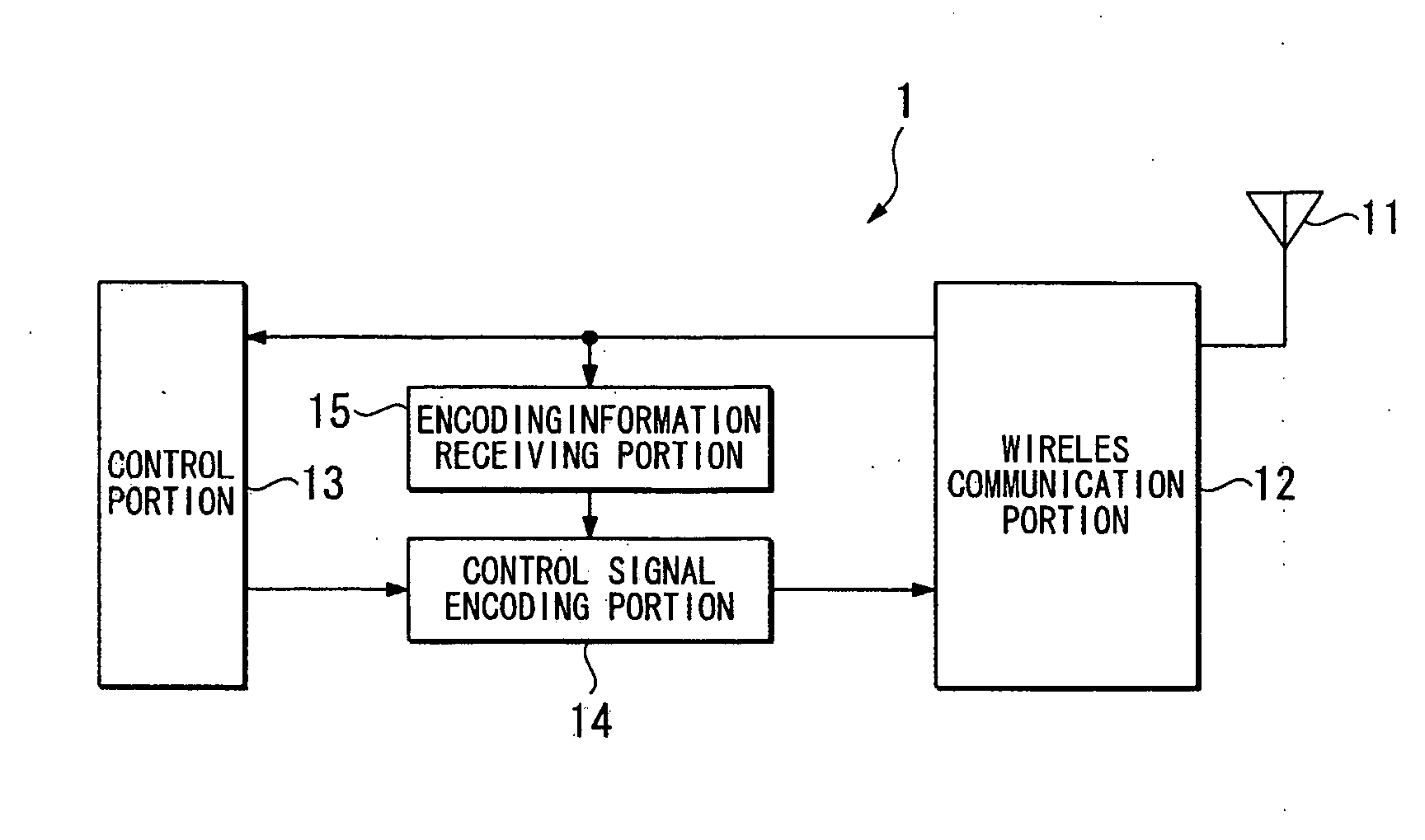
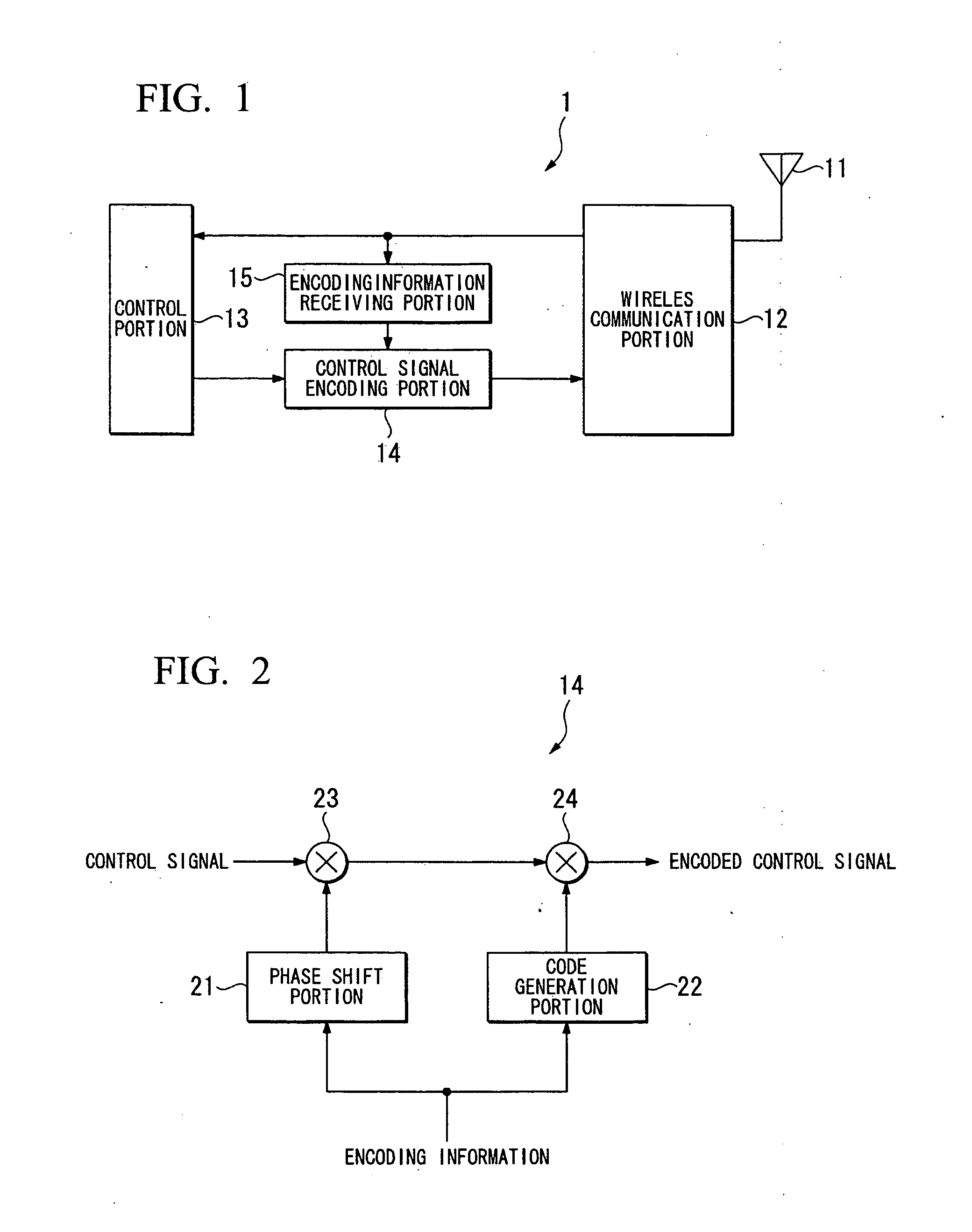
Both a wireless terminal apparatus and wireless base station apparatus are provided that can, in an operation of encoding the control signals of the upstream link transmitted from the multiple terminal stations while encoding with regard to each of the terminal stations, increase a number of the terminal stations to which different codes are respectively assigned. A wireless terminal apparatus includes: an encoding information receiving portion receiving encoding information which is used at the wireless terminal apparatus from the base station; a phase-shifting unit which conducts a phase-shifting operation on a predetermined first code based on the encoding information; a code selection unit which, based on the received encoding information, selects a second code from multiple codes orthogonally crossing each other; and a control signal encoding portion which conducts an encoding operation on the control signal that is going to be transmitted to the base station by using both the first code on which the phase-shifting operation has been conducted and the second code.

Description

TECHNICAL FIELD[0001]The present invention relates to a wireless terminal apparatus and a wireless base station apparatus.[0002]Priority is claimed on Japanese Patent Application No. 2006-296910, filed Oct. 31, 2006, the content of which is incorporated herein by reference.BACKGROUND ART[0003]In recent years, a standardization project “3GPP: 3rd Generation Partnership Project” has been discussing a standard regulation of a third generation (3G) mobile communication system. One of topics which has been discussed is a control signal transmission method of an upstream link (link in a direction from a terminal station to a base station).[0004]For example, Non-Patent Document 1 proposes a method of encoding both ACK / NACK signals transmitted from multiple terminal stations and CQI (Channel Quality Indicator) signals at the upstream link with regard to each of the terminal stations. ACK / NACK signals are response signals of 1 bit for confirmation of transmission, ACK signal has a bit “1” us...

Claims


Application Information

Patent Timeline
Patent Type & Authority Applications(United States)
IPC IPC(8): H04W40/00H04B1/707H04J13/00H04J13/18H04W24/10H04W72/04H04W76/04H04W88/02
CPCH04J13/004H04J13/0074H04J13/18H04W76/04H04W88/02H04J13/0062H04W72/0413H04L5/0014H04J13/0003H04J13/0059H04J11/00H04W76/20H04W72/21H04W72/23H04W72/0466
Inventor YAMAMOTO, TOSHIAKILU, FENGSUZUKI, TOSHINORI
Owner TOYOTA JIDOSHA KK
Learn More