
Image forming apparatus and process cartridge

a technology of image forming apparatus and process cartridge, which is applied in the direction of engine lubrication, lubrication elements, instruments, etc., can solve the problems of difficult uniform surface charge, disadvantageous configuration, and prone to further deformation of cleanability, so as to prevent smearing and high accuracy

Inactive Publication Date: 2009-12-10
RICOH KK
View PDF10 Cites 29 Cited by
  • Summary
  • Abstract
  • Description
  • Claims
  • Application Information

AI Technical Summary

Benefits of technology

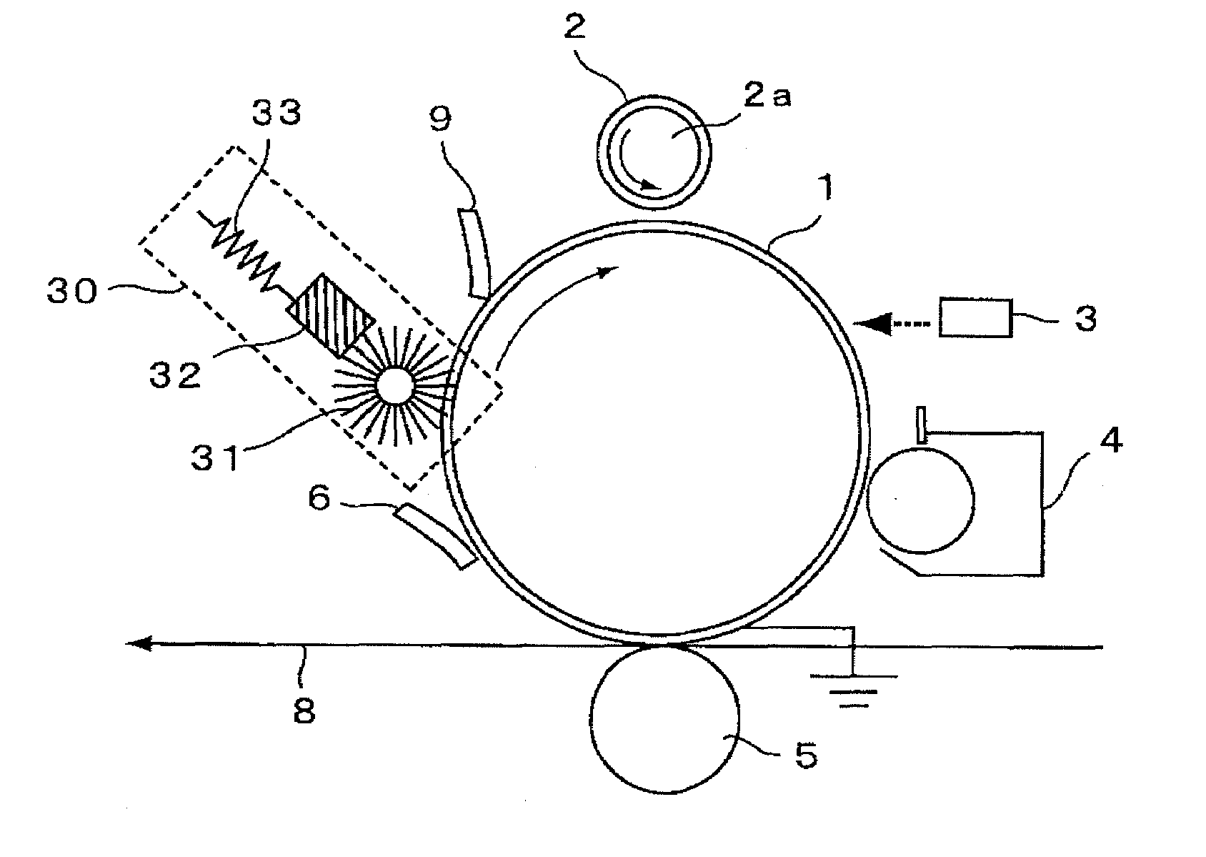
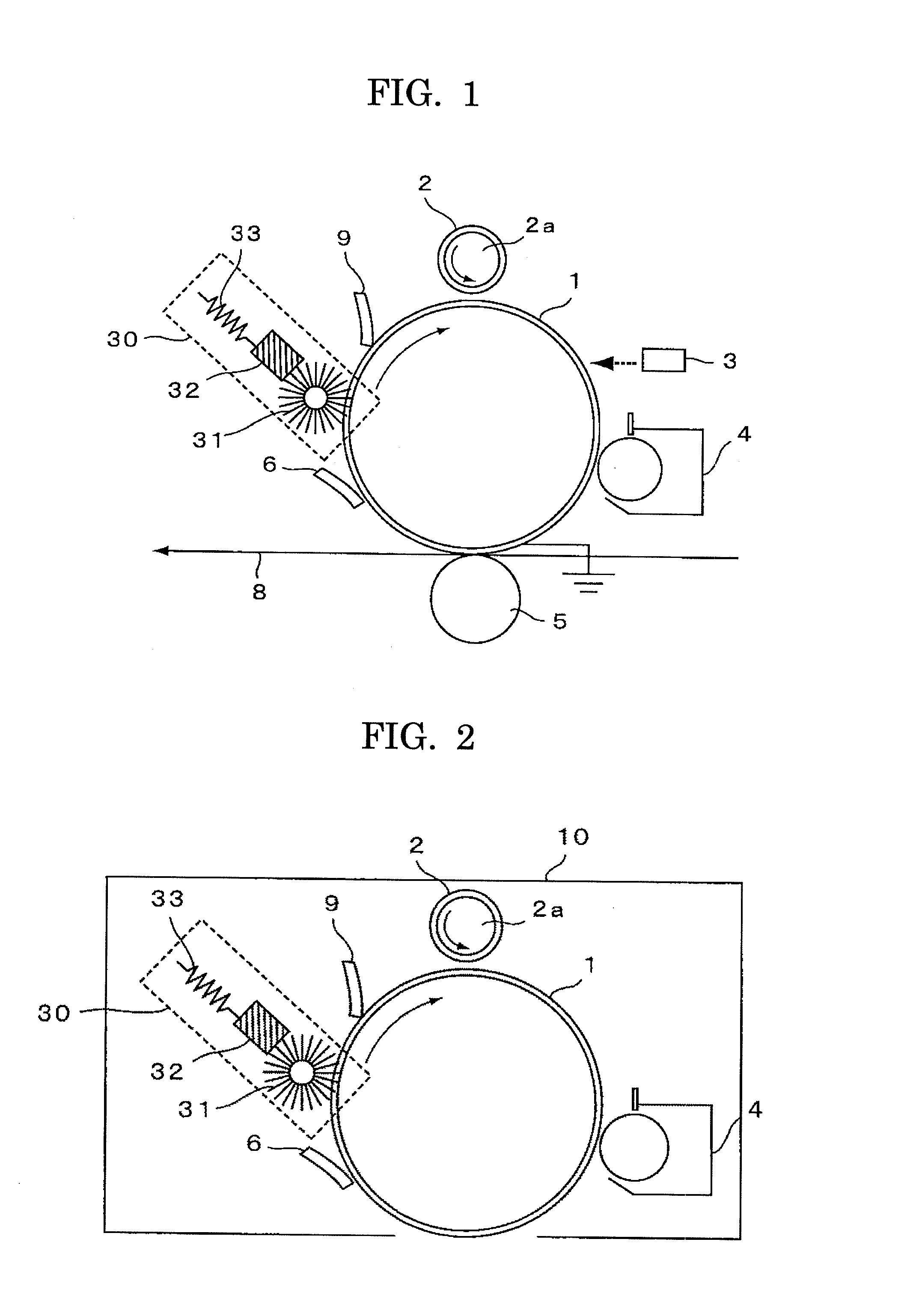
[0019]In view of the above mentioned situation, the present invention has an object to provide an image forming apparatus and a process cartridge having a simple configuration, allowing the downsizing thereof and low-cost production, whereby abrasion of a photoconductor can be prevented, the cleanability of the photoconductor can be maintained even under application of an AC voltage, longer lives of whole members disposed around the photoconductor can be achieved by preventing a charging member from smearing, and images excellent in quality can be output over a long period of time.
[0030]According to the present invention, it is possible to prevent a powdery protecting agent that has been applied onto the surface of an image bearing member from adhering onto a charging member due to the effect of an electric field, and thus the surface of the charging member can be prevented from smearing with high accuracy, and an excellent image having no black streaks can be maintained for a long period of time.

Problems solved by technology

In a charging device employing the close-contact charging (discharging), it is hard to uniformly charge the surface of a photoconductor due to a nonuniform contact between the charging member and the photoconductor or due to an amount of fluctuation of a gap between the charging member and the photoconductor in the case where noncontact charging method is employed.
Such a charging method in which an AC component is superimposed on a DC component, however, activates a photoconductor surface to increase an adhesion force between the photoconductor surface and a toner, and thus from the viewpoint of the cleanability, it is disadvantageous in the configuration.
Moreover, since toner particles are made to be small in diameter and to be more spherical to obtain a high quality image, the cleanability tends to further degrade.
Furthermore, recent studies reveal that since use of a charging method based on close-contact discharging tends to cause deterioration of a photoconductor surface since the photoconductor surface and peripheral portions are concentrically discharged.
Under application of an AC voltage, such a problem with a degradation of cleanability and abrasion resistance of the photoconductor is conspicuous.
These units exhibit an excellent effect of satisfying both the cleanability and the abrasion resistance of a photoconductor, but a new problem arises that the protecting agent itself passes through a cleaning blade and is attached to the charging member.
If a protecting agent that has passed through the cleaning blade is attached to and accumulated on the charging member, the protecting agent shows up as an undesirable abnormal image such as black streaks.
However, in this method, the protecting agent removing unit becomes gradually smeared with time, and the effect of removing the protecting agent is reduced, and this method has not achieved in sufficiently prolonging the life span of a charging member.
In the form of a process cartridge, there is a problem that although photoconductor itself has a long life, it is replaced with a new one in an early stage of life due to the smeared charging member.

Method used


Image

  • Image forming apparatus and process cartridge
  • Image forming apparatus and process cartridge
  • Image forming apparatus and process cartridge

Examples


example 1

[0096]As an evaluation apparatus, a remodeled image forming apparatus of a color complex machine IMAGIO MPC 4500 (manufactured by Ricoh Company Ltd.), in which the black station had been remodeled, was used. As a charging member, a hard resin roller having a diameter of 12 mm was used, and a gap between the charging member and the photoconductor was adjusted to 50 μm.

[0097]As the charge condition, an alternating electric field in which a sinusoidal wave having Vpp of 2.2 kV and a frequency of 1.5 kHz, as an AC component, was superimposed on a DC component having −600 V, was applied to a photoconductor surface.

[0098]A zinc stearate bar as a protecting agent was brought into contact with a cleaning brush so as to supply the photoconductor surface with zinc stearate by the brush.

[0099]A conductive blade as a protecting agent charging member was disposed, in a trailing mode, at a position downstream of the cleaning lo brush and a zinc stearate coating brush and upstream of the charge ro...

example 2

[0101]Evaluation was carried out in the same manner as in Example 1 except that the conductive blade as a protecting agent charging member was disposed in a counter mode.


PUM


Abstract

An image forming apparatus including a charging unit configured to charge a surface of an image bearing member utilizing discharge generated by applying a voltage containing an alternating current component to a charging member disposed in contact with or close to the image bearing member, so that a latent electrostatic image is formed on the image bearing member; a developing unit configured to develop the latent electrostatic image formed on the image bearing member using a toner; a cleaning unit configured to clean the surface of the image bearing member using a blade; a protecting agent applying unit configured to rub and scrape a protecting agent by a brush roller and apply the protecting agent to the surface of the image bearing member; and a protecting agent charging member configured to charge the protecting agent, the member being disposed between the protecting agent applying unit and the charging unit.

Description

BACKGROUND OF THE INVENTION[0001]1. Field of the Invention[0002]The present invention relates to an image forming apparatus such as a complex machine equipped with at least one of a copier, a printer, a facsimile and a plotter, more specifically relates to an image forming apparatus using a process of applying or attaching a protecting agent to the surface of an image bearing member; and a process cartridge detachably mounted to the main body of the image forming apparatus.[0003]2. Description of the Related Art[0004]Conventionally, an image forming apparatus employing an electrophotographic process has a charging unit for charging the surface of a photoconductor as an image bearing member. As one of charging methods used with a charging unit, there is a charging method based on close-contact discharging, in which a charging member is placed in contact or non-contact with the surface of a photoconductor, and the surface of the photoconductor is charged by close-contact discharging.[...

Claims


Application Information

Patent Timeline
Patent Type & Authority Applications(United States)
IPC IPC(8): G03G21/00
CPCG03G21/0094
Inventor OZAKI, NAOYUKINAKAI, HIROSHIYAMASHITA, MASAHIDEIIO, MASATOTANAKA, SHINYAHASEGAWA, KUNIO
Owner RICOH KK
Learn More