
Cargo transport system and method

a transportation system and cargo technology, applied in the field of cargo handling, can solve the problems of reducing the payload or range, affecting the safety of passengers, and the hardware of cargo handling of significant weight is still needed to move, so as to simplify loading operations, reduce the weight of the floor structure of the cargo bay, and enhance safety

Active Publication Date: 2009-12-10
THE BOEING CO
View PDF18 Cites 43 Cited by
  • Summary
  • Abstract
  • Description
  • Claims
  • Application Information

AI Technical Summary

Benefits of technology

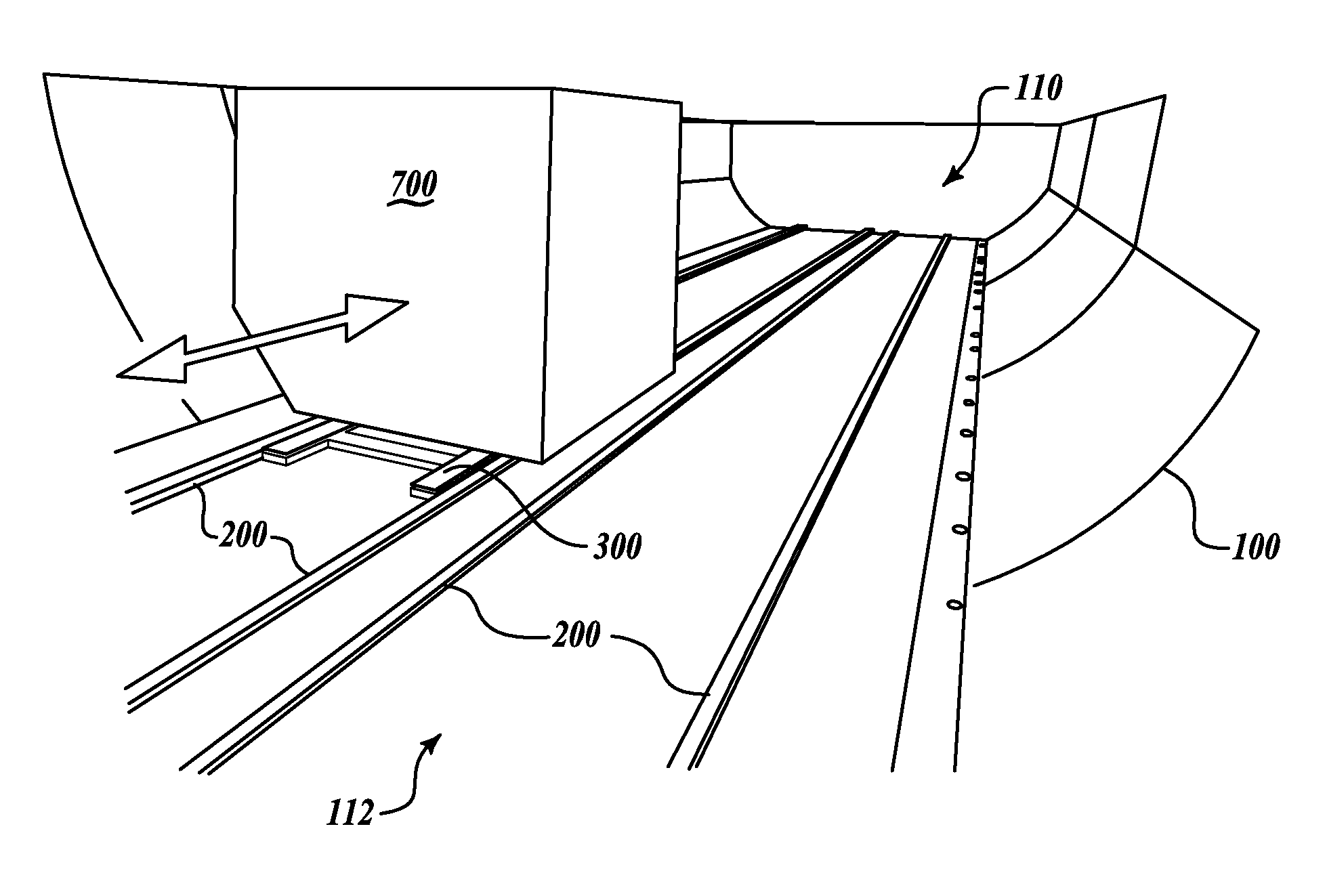
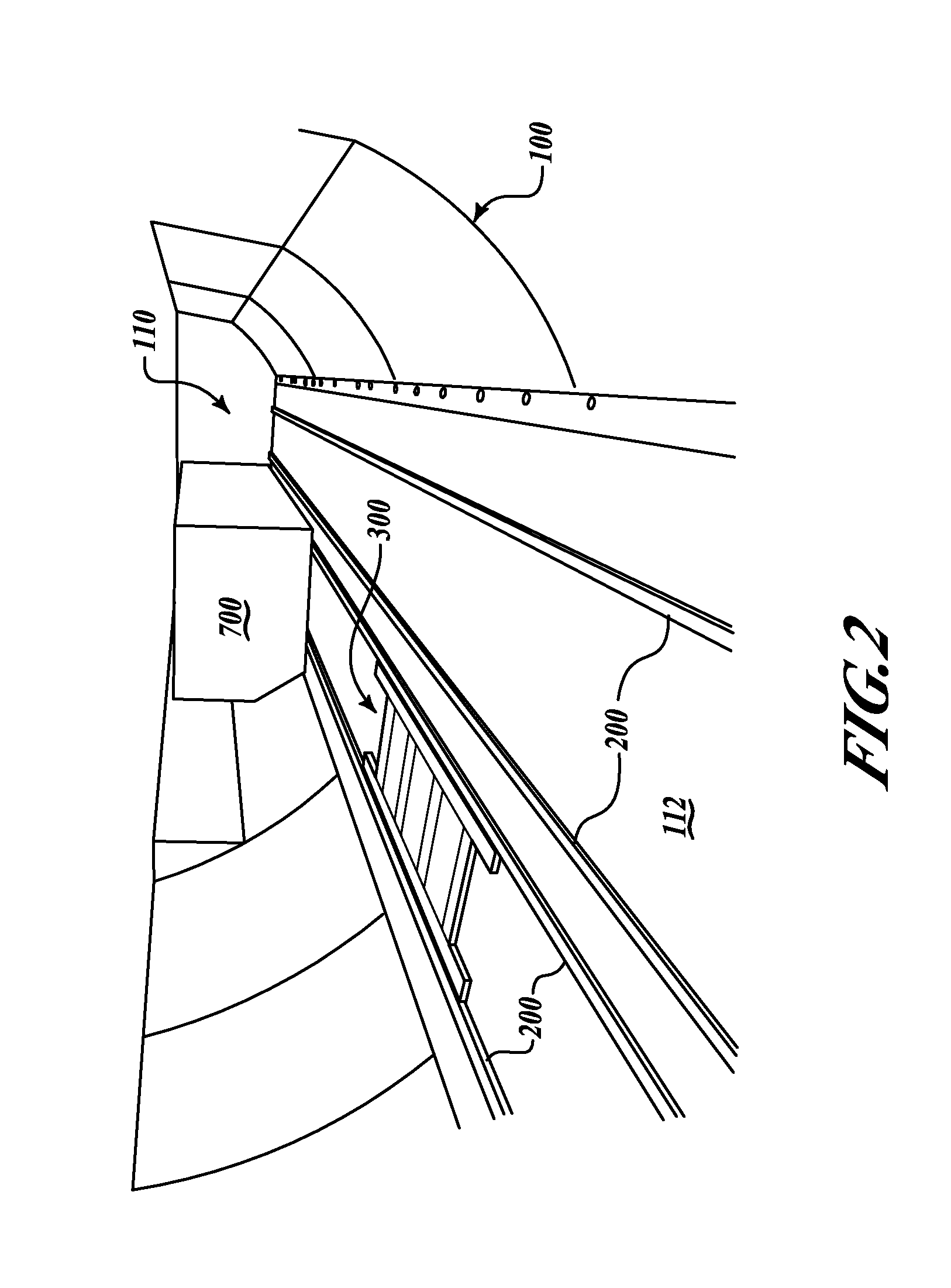
[0005]The invention provides a system and method of loading cargo onto a vehicle, and offloading cargo containers from the vehicle, that has many advantages. In the case of aircraft, the advantages include the reduction in weight of onboard cargo bay floor structure for transport of cargo containers, and the simplification of loading operations by guided cargo container loading that enhances safety and improves loading efficiency by reducing time for loading. The reduction in onboard weight increases potential payload and / or range thereby increasing revenues. Further, this invention simplifies the floor-mounted equipment required for cargo handling, thus resulting in a reduced installation time, reduced maintenance time, and increased reliability. This simplified floor also has fewer penetrations, simplifying cleaning operations. Further, this invention may reduce damage to airplane and cargo containers by reducing the generation of metal shavings that current cargo handling systems produce when cargo containers collide into one another under current cargo loading procedures. Embodiments of the invention may be readily retrofitted to aircraft already in use or can be original equipment in new aircraft. This invention can also be applied to other forms of cargo transport or relocation on other types of vehicles or ground transportation.

Problems solved by technology

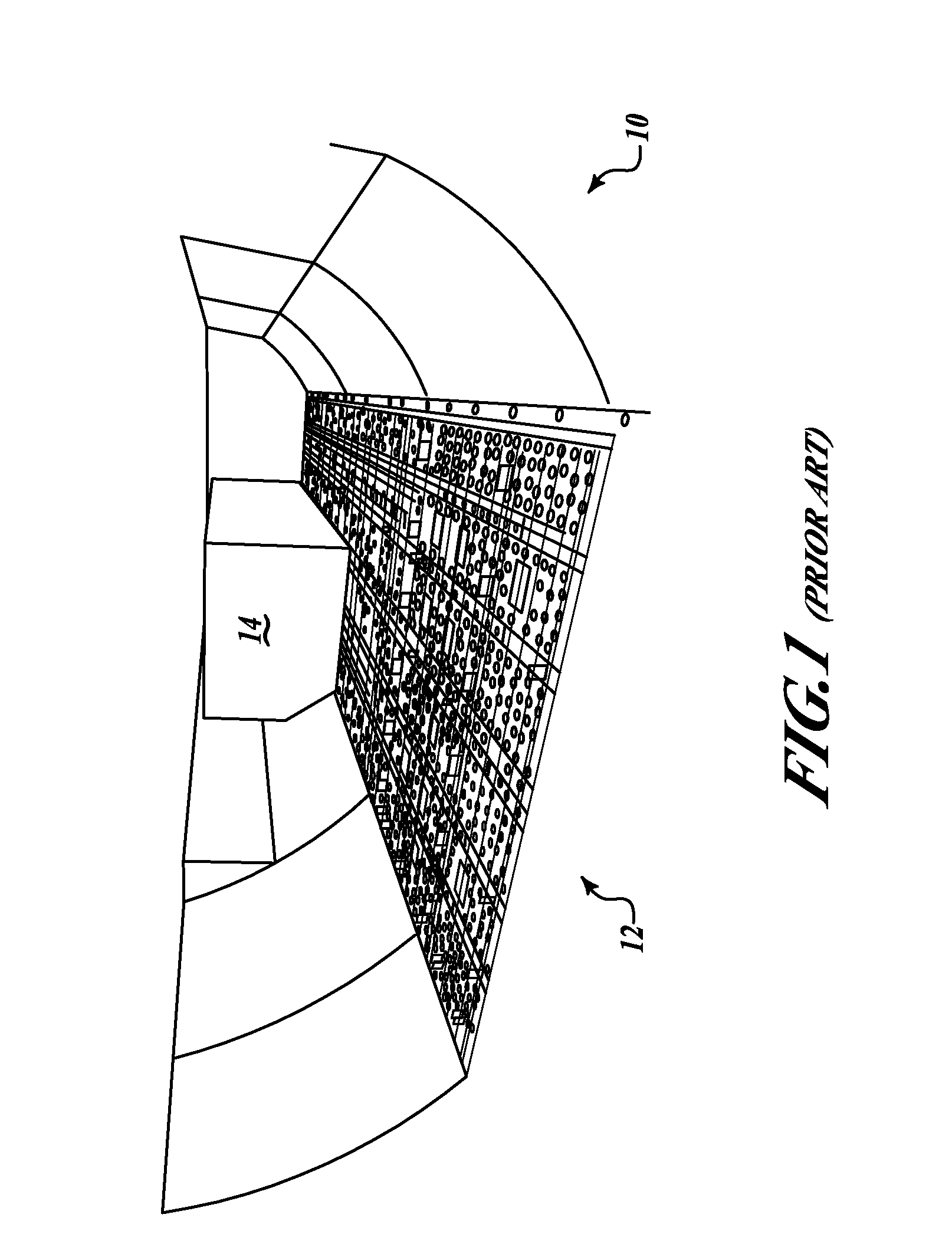
The mechanisms and structure depicted on cargo bay floor 12 adds significant weight to the structure of the airframe, of the order of about 15,000 pounds in some cases, and results in reduced payload or range.
In addition, moving cargo containers within the airframe sometimes causes damage to the floor structure as cargo containers are moved about on a roller system and power drive wheels.
However, cargo handling hardware of significant weight is still needed to move and support cargo within the airplane cargo hold.

Method used


Image

  • Cargo transport system and method
  • Cargo transport system and method
  • Cargo transport system and method

Examples


Embodiment Construction

[0024]The following detailed description is merely illustrative in nature and is not intended to limit the invention or the application and uses of the invention. Furthermore, there is no intention to be bound by any expressed or implied theory presented in the preceding technical field, background, brief summary or the following detailed description.

[0025]The invention may be described herein in terms of functional and / or logical block components and various processing steps. It should be appreciated that such block components may be realized by any number of hardware, software, and / or firmware components configured to perform the specified functions. For example, an embodiment of the invention may employ various integrated circuit components, e.g., memory elements, digital signal processing elements, logic elements, look-up tables, or the like, which may carry out a variety of functions under the control of one or more microprocessors or other control devices. In addition, those s...


PUM


Abstract

A system for loading cargo containers into a storage hold, and offloading cargo containers from the storage hold, especially of a vehicle, such as an aircraft. The system includes at least one guide rail and a motorized platform, onto which cargo containers are loaded, cooperating mechanically with the guide rail. The guide rail guides the cargo laden motorized platform into the storage hold, and the motorized platform deposits the cargo upon remote command. The motorized platform has a chassis; a power source; a control module controlling drive motors of the wheels of the platform; and means for reciprocating at least a portion of an upper surface of the platform sufficient to elevate a load placed thereon above the guide rail height.

Description

TECHNICAL FIELD[0001]The present invention relates generally to the field of cargo handling on large cargo carrying vehicles. More particularly, the invention provides a guided motorized platform system useful in loading and transporting loading cargo containers within aircraft and other vehicles that eliminates the need for the vehicle to carry cargo handling equipment.BACKGROUND[0002]Movement of cargo containers or cargo pallets within an airplane structure requires a complex system of airplane-mounted drive motors, roller trays, latch mechanisms and support structure. Some of this support structure is depicted for illustrative purposes, in perspective view in FIG. 1, showing a portion of a cargo floor 12 of an aircraft 10 containing a cargo container 14. The mechanisms and structure depicted on cargo bay floor 12 adds significant weight to the structure of the airframe, of the order of about 15,000 pounds in some cases, and results in reduced payload or range. In addition, moving...

Claims


Application Information

Patent Timeline
IPC IPC(8): B60P1/02
CPCB64D9/00Y02T50/46B64D2009/006Y02T50/40B65G67/00B65G69/24
Inventor SANFORD, WILLIAM C.LAIB, TREVORMITCHELL, BRADSANCHEZ, JESUSMACKNESS, ROBERTMACKNESS, PRESTONFLETCHER, HENRY V.CALLAHAN, KEVIN S.
Owner THE BOEING CO
Learn More