Locomotive-radiator-cooling-fan tankhead assembly

a technology of radiator and tank head, which is applied in the direction of positive displacement liquid engine, liquid fuel engine, piston pump, etc., can solve the problem of unfavorable contact between the fan blade tip and the surrounding fan-frame ring

Inactive Publication Date: 2009-12-10
DAYTON PHOENIX GROUP
View PDF6 Cites 1 Cited by
  • Summary
  • Abstract
  • Description
  • Claims
  • Application Information

AI Technical Summary

Problems solved by technology

It is noted that applicants' shock and vibration testing of a conventional locomotive radiator cooling fan, having a conventional tankhead assembly design, which replaced the steel with an aluminum alloy for the tankhead assembly, the vanes, the fan-frame ring, and the hub assembly including the blades resulted in the tankhead assembly exhibiting a wobble mode during a static (motor switched off) vibration test of the cooling fan, wherein the test subjected the cooling fan to eight hours of 2-g load vibration at resonance frequencies and resulted in undesirable contact of the fan blade tips with the surrounding fan-frame ring.

Method used


Image

  • Locomotive-radiator-cooling-fan tankhead assembly
  • Locomotive-radiator-cooling-fan tankhead assembly
  • Locomotive-radiator-cooling-fan tankhead assembly

Examples


Embodiment Construction

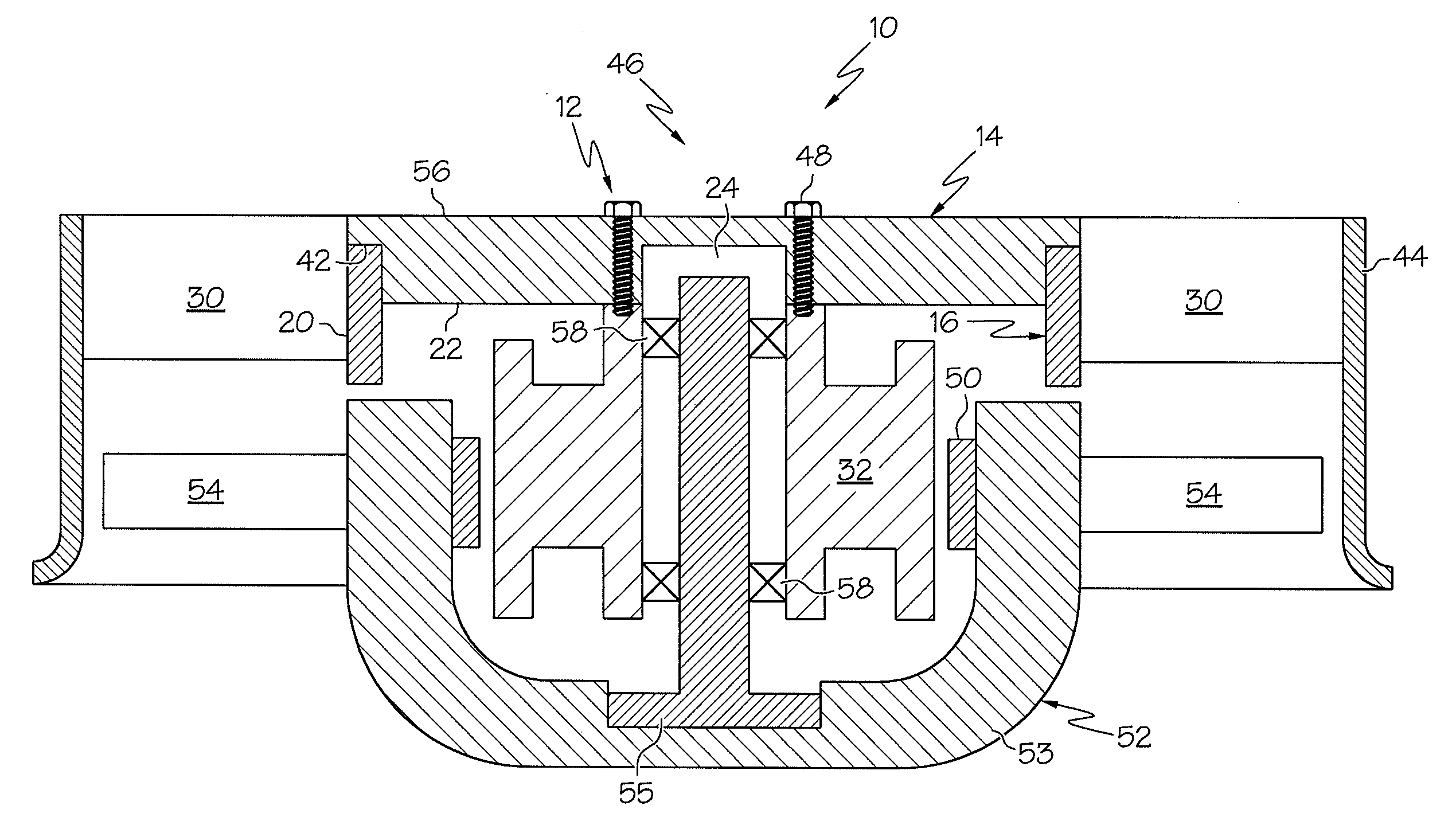
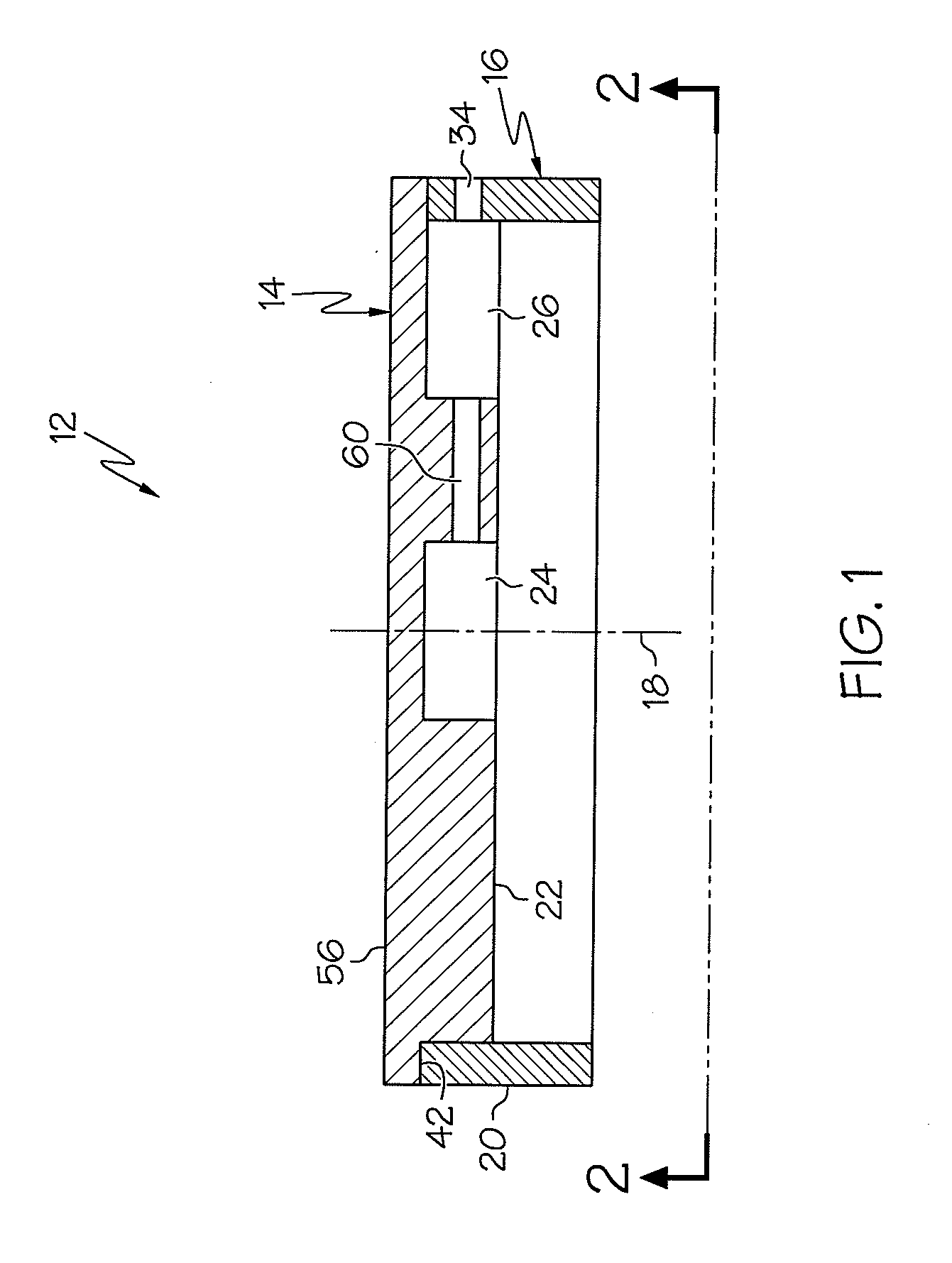
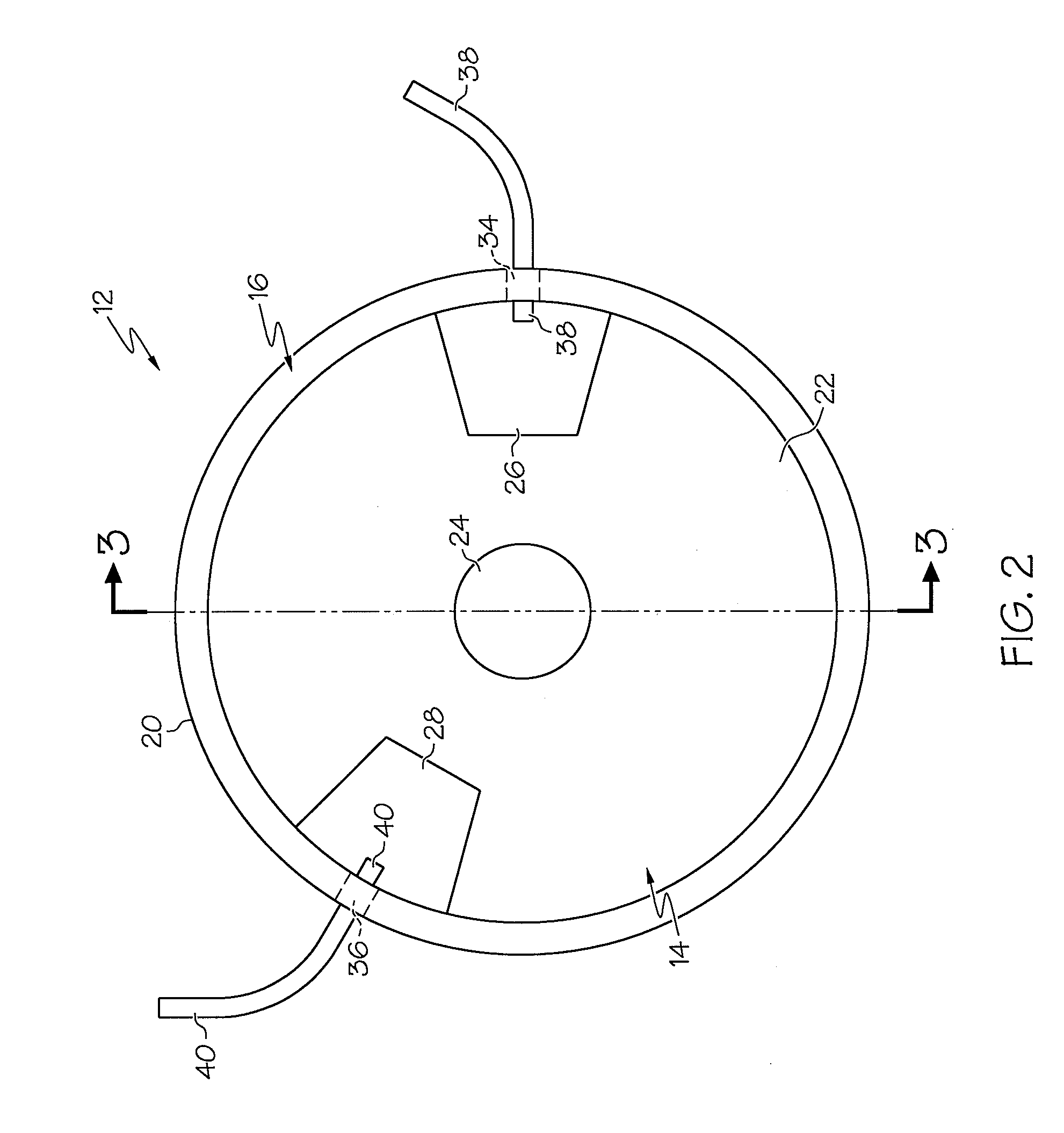
[0012]Referring now to the drawings, FIGS. 1-4 show an embodiment of the present invention. A first expression of the embodiment of FIGS. 1-4 is for apparatus including a locomotive-radiator-cooling-fan tankhead assembly 12. The tankhead assembly 12 has a substantially-circular base plate 14 and a substantially-circular outer ring 16. The base plate 14 and the outer ring 16 each consist essentially of an aluminum alloy. A maximum diameter of the base plate 14 divided by a maximum thickness of the base plate 14 is between 5 and 15, and the maximum diameter of the base plate 14 divided by a maximum thickness of the outer ring 16 is between 20 and 30. The base plate 14 has a central longitudinal axis 18 and a circumference 20. The outer ring 16 is substantially coaxially aligned with the central longitudinal axis 18 and is attached to the base plate 14 proximate the circumference 20. The base plate 14 has a substantially-planar first surface 22 having a central recess 24 substantially ...


PUM


Abstract

Apparatus including a locomotive-radiator-cooling-fan tankhead assembly having a substantially-circular base plate and a substantially-circular outer ring. The base plate has a central longitudinal axis and a circumference. The outer ring is substantially coaxially aligned with the central longitudinal axis and is attached to the base plate proximate the circumference. The base plate has a substantially-planar first surface having a central recess substantially coaxially aligned with the central longitudinal axis and having circumferentially-separated, first and second peripheral recesses each radially spaced apart from the central recess and extending radially inward from proximate the circumference. The outer ring longitudinally extends beyond the first surface. The tankhead assembly is devoid of any gussets attached to the base plate and is devoid of any gussets attached to the outer ring.

Description

CROSS REFERENCE TO RELATED APPLICATIONS[0001]The present application claims priority of U.S. Provisional Application No. 61 / 060,219 filed Jun. 10, 2008.TECHNICAL FIELD[0002]The present invention relates generally to locomotives, and more particularly to a locomotive-radiator-cooling-fan tankhead assembly.BACKGROUND OF THE INVENTION[0003]Conventional tankhead assemblies of locomotive radiator cooling fans are made of steel and consist of a circular base plate, a circular inner ring, a circular outer ring, and a plurality of gussets. The inner and outer rings are welded to a substantially-planar first surface of the base plate. The base plate and the outer ring have a thickness of ⅜-inch, and the base plate has a diameter of 24 or 26 inches. The process of assembling a locomotive radiator cooling fan includes welding non-rotatable steel vanes to the outer ring of the tankhead assembly and bolting a fan-motor stator assembly to the base plate of the tankhead assembly, wherein an annula...

Claims


Application Information

Patent Timeline
Patent Type & Authority Applications(United States)
IPC IPC(8): F04D25/06F04D29/40
CPCF04D29/542F04D25/0613
Inventor ZAHORA, JOSEPH A.YU, JOHNNY D.
Owner DAYTON PHOENIX GROUP
Why Eureka
Try Eureka