Apparatus, system, and method for generating a gas from solid reactant pouches

a solid reactant and gas technology, applied in the direction of electrochemical generators, chemical/physical/physicochemical processes, chemical apparatus and processes, etc., can solve the problems of unresolved problems such as the inability to control the chemical reaction between reactants without adversely affecting the gravimetric and volumetric energy density of the overall system, and the inability to produce pure gasses using conventional methods is generally cost prohibitiv

Inactive Publication Date: 2009-12-10
TRULITE INC
View PDF99 Cites 395 Cited by
  • Summary
  • Abstract
  • Description
  • Claims
  • Application Information

AI Technical Summary

Benefits of technology

[0024]Furthermore, the described features, advantages, and characteristics of the invention may be combined in any suitable manner in one or more embodiments. One skilled in the relevant art will recognize that the invention may be practiced without one or more of the specific features or advantages of a particular embodiment. In other instances, additional features and advantages may be recognized in certain embodiments that may not be present in all embodiments of the invention.
[0025]These features and advantages of the present invention will become more fully apparent from the following description and appended claims, or may be learned by the practice of the invention as set forth hereinafter.

Problems solved by technology

Producing pure gasses using conventional methods is generally cost prohibitive or requires storing the gas at high pressures.
Unfortunately, there are several unresolved problems producing pure gasses from chemical reactions.
Specifically, conventional systems, methods, and apparatuses have not successfully controlled chemical reactions between reactants without adversely affecting the gravimetric and volumetric energy density of the overall system.
This lack of control also prevents conventional systems, methods, and apparatuses from meeting dynamic gas demands of new devices like PEM fuel cells.
Many chemical reactions that produce gasses are very severe and highly exothermic.
Many failed attempts have been made to properly control the reactions while still preserving the gravimetric and volumetric energy density provided by the reactants.
This is inefficient and greatly increases the amount of reactants that such systems use to create a given amount of gas.

Method used


Image

  • Apparatus, system, and method for generating a gas from solid reactant pouches
  • Apparatus, system, and method for generating a gas from solid reactant pouches
  • Apparatus, system, and method for generating a gas from solid reactant pouches

Examples


Embodiment Construction

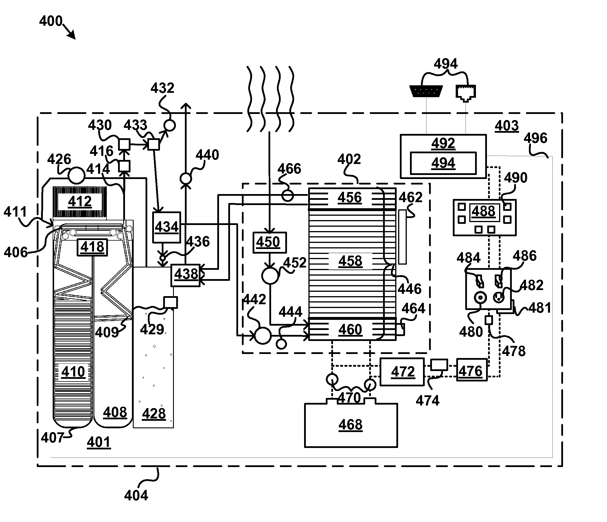
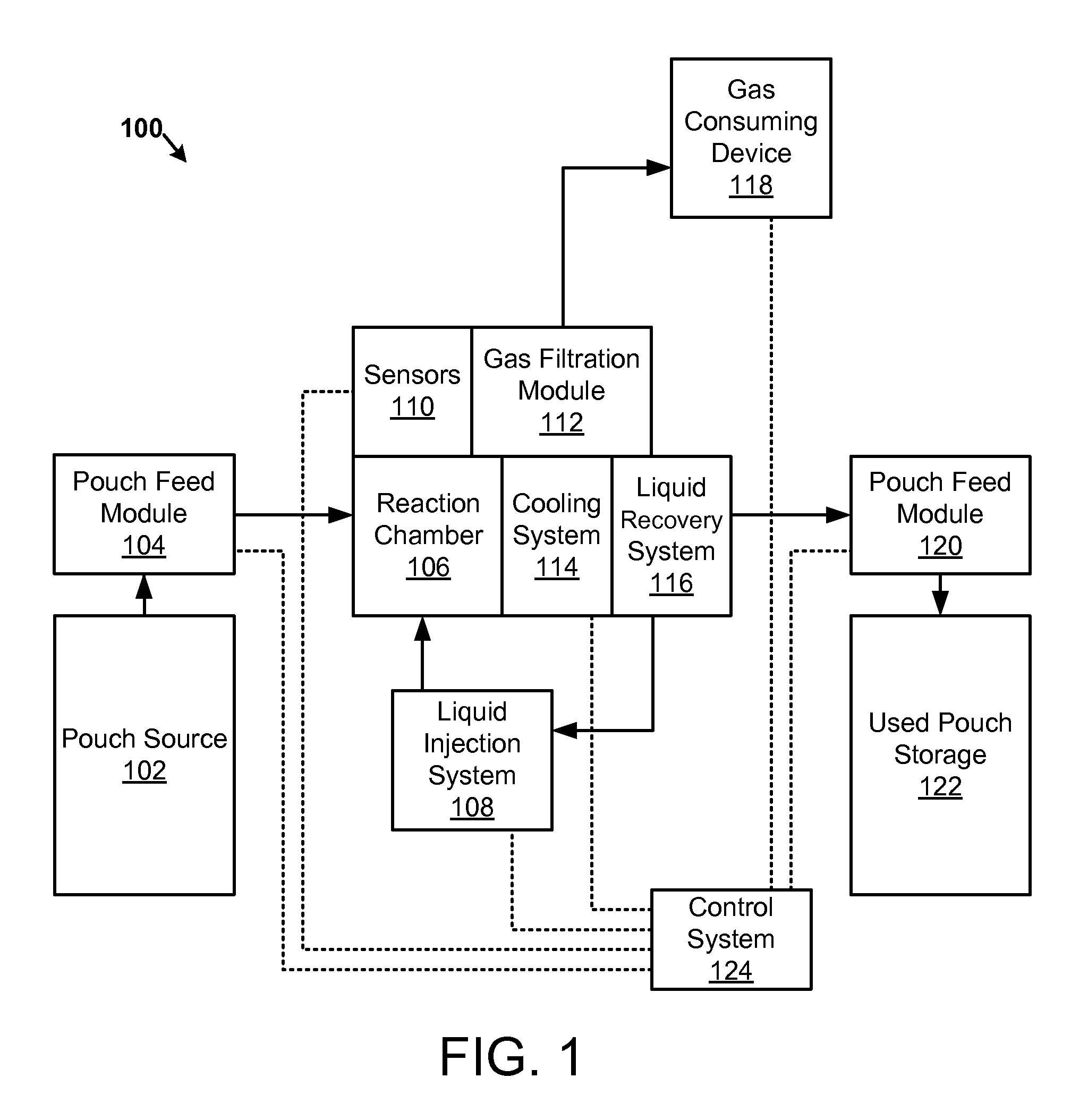
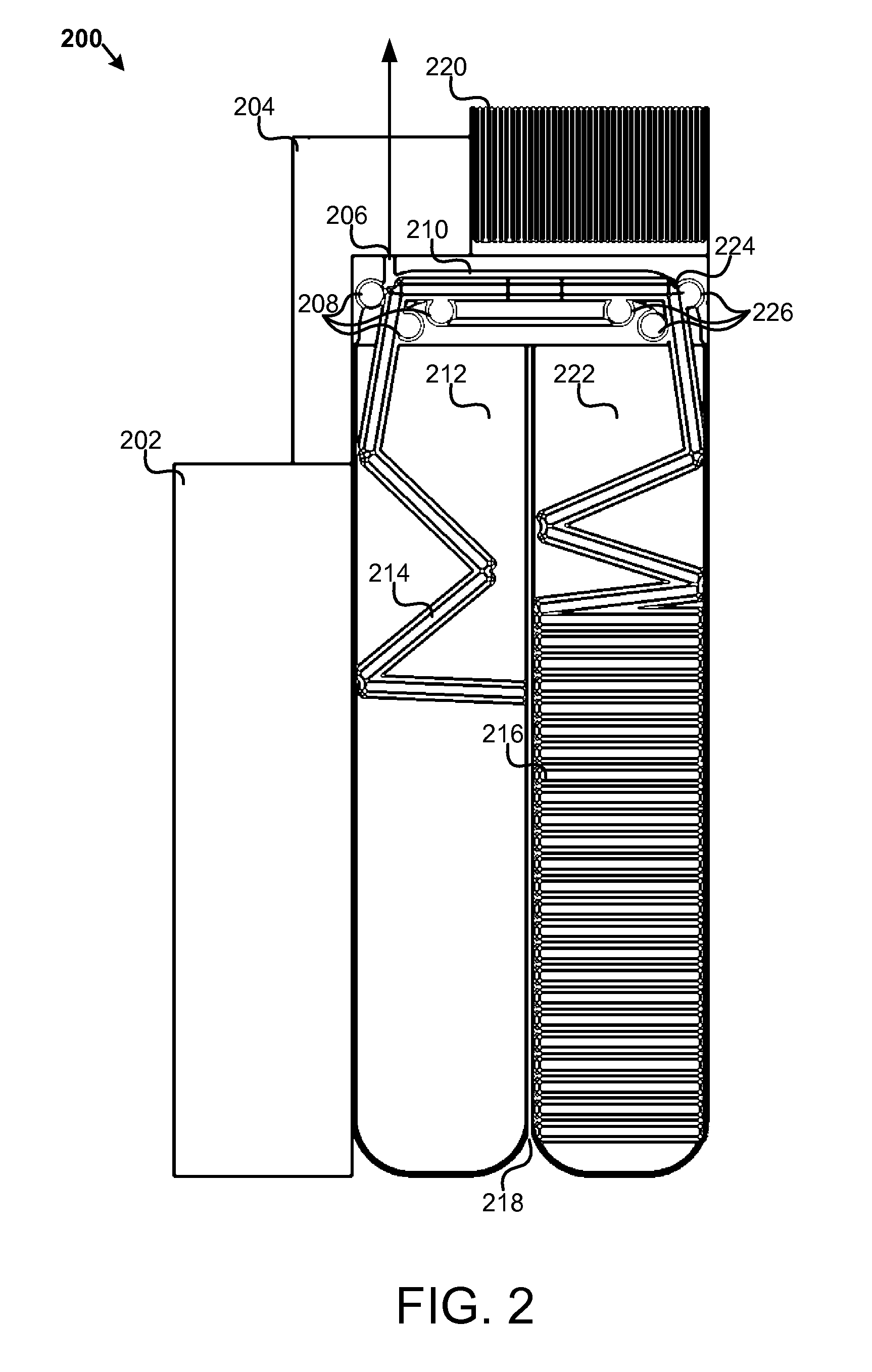
[0032]Reference throughout this specification to “one embodiment,”“an embodiment,” or similar language means that a particular feature, structure, or characteristic described in connection with the embodiment is included in at least one embodiment of the present invention. Thus, appearances of the phrases “in one embodiment,”“in an embodiment,” and similar language throughout this specification may, but do not necessarily, all refer to the same embodiment.

[0033]Furthermore, the described features, structures, or characteristics of the invention may be combined in any suitable manner in one or more embodiments. In the following description, numerous specific details are presented to provide a thorough understanding of embodiments of the invention. One skilled in the relevant art will recognize, however, that the invention may be practiced without one or more of the specific details, or with other methods, components, materials, and so forth. In other instances, well-known structures,...


PUM

PropertyMeasurementUnit
temperaturesaaaaaaaaaa
thicknessaaaaaaaaaa
thicknessaaaaaaaaaa

Abstract

An apparatus, system, and method are disclosed for generating a gas. One or more liquid permeable pouches each define a cavity that contains a solid anhydrous reactant, such as a chemical hydride. A reaction chamber made of a heat, chemical and/or pressure resistant material receives the one or more pouches from a pouch feeder that transfers the one or more pouches into the reaction chamber successively at a feed rate. One or more liquid sources inject a liquid reactant into the reaction chamber so that the liquid reactant contacts a portion of the one or more pouches. The one or more liquid sources inject the liquid reactant at an injection rate that corresponds to the feed rate. A gas outlet releases a gas, such as hydrogen, oxygen, ammonia, borazine, nitrogen, or a hydrocarbon, that is produced by a reaction between the solid reactant and the liquid reactant.

Description

CROSS-REFERENCES TO RELATED APPLICATIONS[0001]This application claims priority to U.S. Provisional Patent Application Ser. No. 61 / 059,743 entitled “Apparatus, System, and Method for Generating Hydrogen from a Feed of Hydride Pouches” filed on Jun. 6, 2008, is a continuation-in-part of and claims priority to U.S. patent application Ser. No. 11 / 740,349 entitled “Apparatus, System, and Method for Promoting a Substantially Complete Reaction of an Anhydrous Hydride Reactant” filed on Apr. 26, 2007 having a priority date of Jun. 11, 2003, and incorporates by reference U.S. patent applications Ser. No. 10 / 459,991 filed Jun. 11, 2003, Ser. No. 11 / 270,947 filed Nov. 12, 2005, Ser. No. 11 / 828,265 filed Jul. 25, 2007, Ser. No. 11 / 829,019 filed Jul. 26, 2007, Ser. No. 11 / 829,035 filed Jul. 26 / 2007, Ser. No. 60 / 951,903 filed Jul. 25, 2007, Ser. No. 60 / 951,907 filed Jul. 25, 2007, Ser. No. 60 / 951,925 filed Jul. 25, 2007 each of which is incorporated by reference herein in its entirety.BACKGROUND ...

Claims


Application Information

Patent Timeline
Patent Type & Authority Applications(United States)
IPC IPC(8): B01J19/00C01C1/00
CPCB01J7/02B01J2208/00106B01J2208/00371B01J2208/00752H01M8/04201B01J2208/00814C01B3/065C01B2203/066Y02E60/362B01J2208/00761Y02E60/36Y02E60/50
Inventor PATTON, JOHN MADISONANDERSON, HOWARD
Owner TRULITE INC
Why Eureka
Try Eureka