Electronic endoscope

Active Publication Date: 2009-12-10
FUJIFILM CORP
View PDF6 Cites 25 Cited by
  • Summary
  • Abstract
  • Description
  • Claims
  • Application Information

AI Technical Summary

Benefits of technology

[0014]According to the present invention, the signal line is pulled out of the coaxial cable longer than the ground line. Each signal line is joined to the corresponding input/output terminal with a larg

Problems solved by technology

Thus, deformation stress applied to the cable bundle causes a break of a joint between the terminal of the printed circuit board and the coaxial cable.
Since t

Method used


Image

  • Electronic endoscope
  • Electronic endoscope
  • Electronic endoscope

Examples


Embodiment Construction

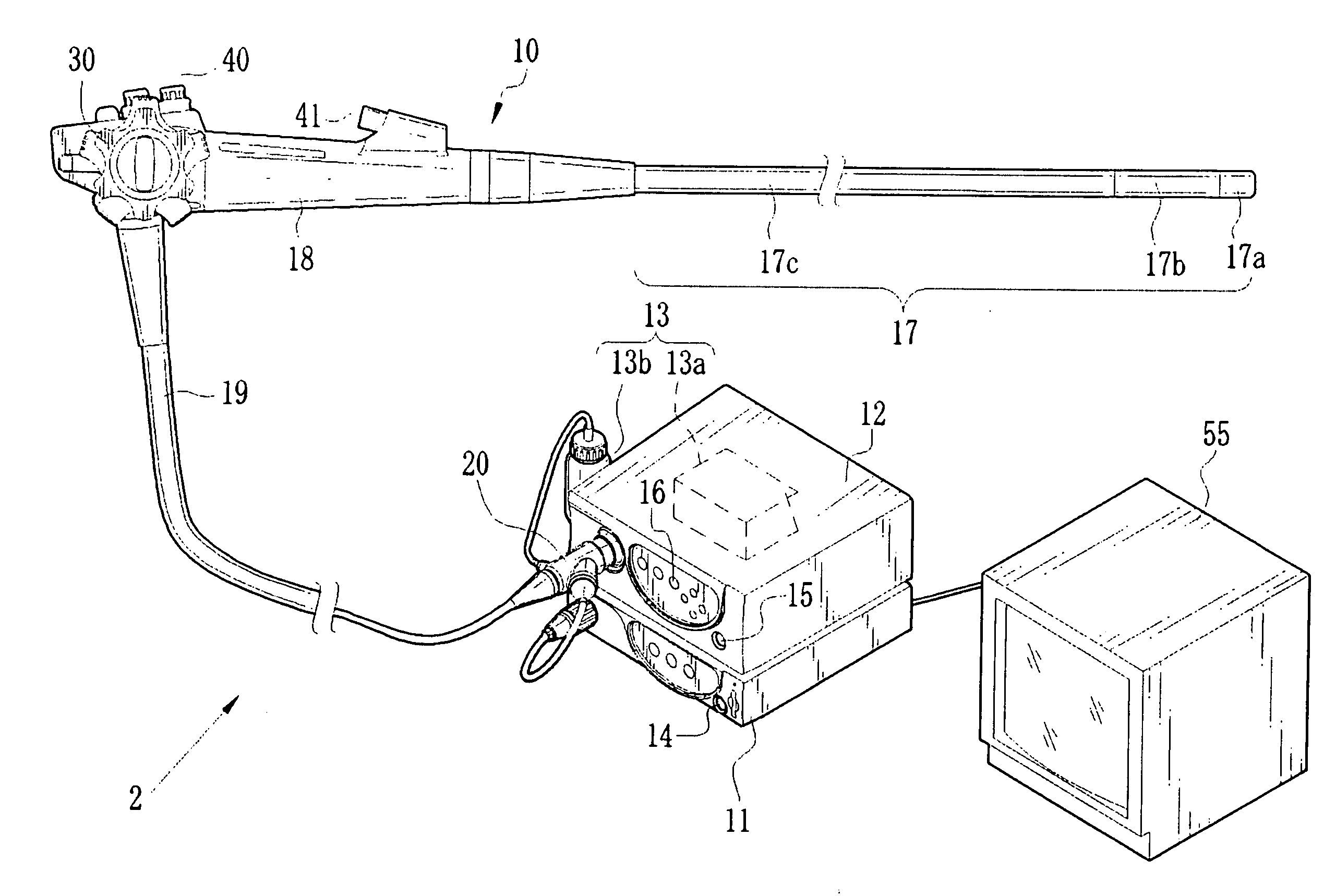
[0028]As shown in FIG. 1, an endoscope system 2 is constituted of an electronic endoscope 10, a processor device 11, a light source device 12, and an airing / watering device 13. The airing / watering device 13 includes a commonly-known airing unit 13a for feeding air and a wash water tank 13b as a reservoir. The airing unit 13a is contained in the light source device 12, and the wash water tank 13b is provided outside the light source device 12. A power switch 14 is provided on a front face of the processor device 11 to turn the processor device 11 on and off. A front face of the light source device 12 is provided with a power switch 15 for turning the light source device 12 on and off and a light switch 16 for turning a light source (not illustrated) on and off.

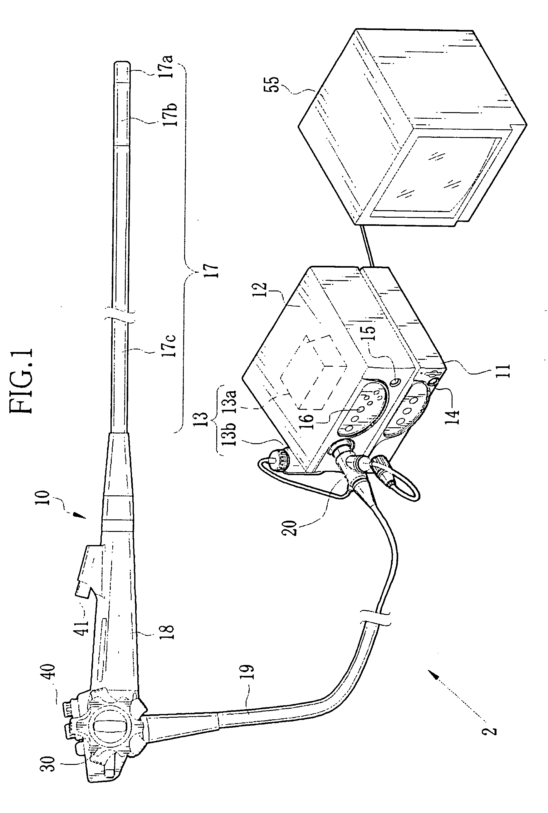
[0029]The electronic endoscope 10 is constituted of an insert section 17 to be inserted into a human body cavity, an operation section 18 coupled to a base end of the insert section 17, and a universal cord 19 connected to the ...


PUM


Abstract

An electronic endoscope has an insert section to be introduced into a human body cavity. A distal portion of the insert section contains a CCD and a printed circuit board to which the CCD is bonded. In the insert section, a cable bundle being a bundle of coaxial cables extends. Each coaxial cable consists of a signal line, insulation surrounding the signal line, a braided wire surrounding the insulation, and an insulating jacket. The cylindrical braided wire is stranded into a single line, and is soldered as a ground line to a ground terminal of the printed circuit board. The signal line is pulled out of the coaxial cable with a length longer than the ground line. The signal line is soldered to an input/output terminal of the printed circuit board with a larger sag than the ground line.

Description

BACKGROUND OF THE INVENTION[0001]1. Field of the Invention[0002]The present invention relates to an electronic endoscope, and especially relates to the electronic endoscope having a connection structure between a coaxial cable and a solid-state image sensor.[0003]2. Description Related to the Prior Art[0004]An electronic endoscope has an insert section to be introduced into a human body cavity and an operation section for operating the insert section. The insert section is constituted of a distal portion, a bending portion, and a flexible portion arranged in this order from a distal end thereof. The distal portion is provided with an image capturing window, lighting windows, a medical instrument outlet, an airing / watering nozzle, and the like. Turning an angle knob on the operation section flexibly bends the bending portion from side to side and up and down to direct the distal portion in a desired direction inside the human body cavity.[0005]The distal portion contains a solid-stat...

Claims


Application Information

Patent Timeline
IPC IPC(8): A61B1/04
CPCA61B1/05A61B1/051H01R9/0515H05K2201/10356H05K1/0243H05K3/3405H05K2201/09809H05K1/0219
Inventor YAMAMOTO, GOKITAKAHASHI, KAZUAKIYASHIRO, TAKASHIKITANO, RYOUYAMAMOTO, KAZUSHIGE
Owner FUJIFILM CORP
Why Eureka
Try Eureka