Polyaxial bone screw

a polyaxial bone screw and screw technology, applied in the field of spinal implant systems, can solve the problems of bone screw exerting unpredictable forces, limited positioning, and large saddle, and achieve the effects of convenient use, reliable, and simple positioning

Inactive Publication Date: 2009-12-10
ORTHO INNOVATIONS
View PDF99 Cites 82 Cited by
  • Summary
  • Abstract
  • Description
  • Claims
  • Application Information

AI Technical Summary

Benefits of technology

[0039]It is another objective of the present invention to provide a polyaxial bone screw assembly for a spinal fixation system that permits component adjustment during installation, thereby enabling satisfactory correction of a wide variety of spinal deformities.
[0040]It is still another objective of the present invention to provide a simple, easy to use, reliable and cost effective implant system.
[0041]It is an additional objecti

Problems solved by technology

Unfortunately, known spinal implant systems often correct one set of problems only to create new ones.
While bone screws are commonly used for anchoring, they are limited in their positioning due to the design of component pieces.
A problem with specially designed clamps is that bone structure cannot be determined until the patient's bone is exposed causing the necessity of a large inventory of various sized clamps to be on hand during surgery because the screws and claims are typically pre-assembled with respect to size, e.g. a larger screw requires a larger clamp, during assembly of the screw and the saddle.
A further limitation of the prior art relates to the requirement of a larger saddle for larger screw diameters.
The larger saddle complicates the placement of the screw to prevent impingement to adjacent body structures.
The result is a bone screw which exerts unpredictable forces upon attachment to component connectors.
Further, any movement of muscle and other tissue increases the difficulty of the operation and can be a major trauma to a person.
A problem with the screw is the need for the locking pin and the inability of the base screw to accommodate a threaded extension bolt.
Unfortunately, although these so-called rigid screw fixation systems can alter the curvature of a patient's spine, they can also be difficult to install.
As a result, the number of suitable anchoring locations is limited.
Achieving a proper fit between all of the components while contending with the constraints encountered during surgery is often difficult.
In severe cases, a suitable fit may not be achieved and the surgery will be unsuccessful.
Additionally, the nature of the installation process requ

Method used


Image

  • Polyaxial bone screw
  • Polyaxial bone screw
  • Polyaxial bone screw

Examples


Embodiment Construction

[0073]It is to be understood that while a certain form of the invention is illustrated, it is not to be limited to the specific form or arrangement of parts herein described and shown. It will be apparent to those skilled in the art that various changes may be made without departing from the scope of the invention and the invention is not to be considered limited to what is shown in the drawings and described in the specification.

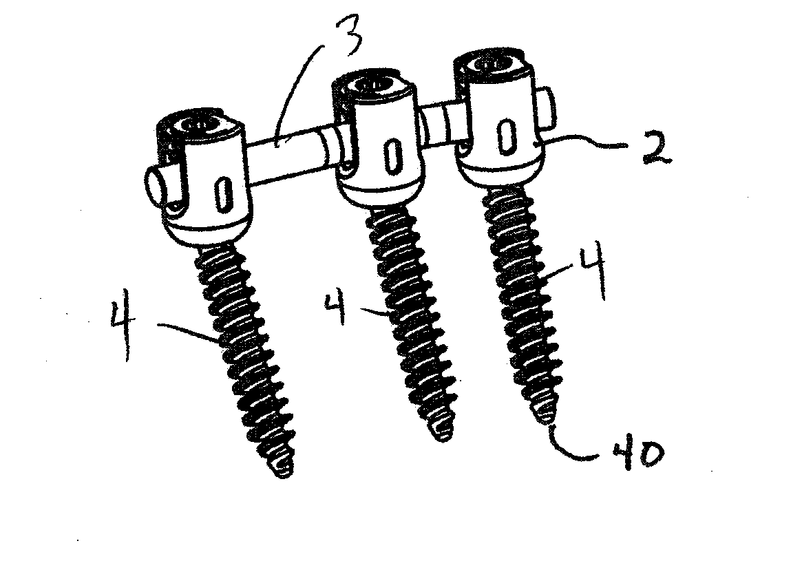
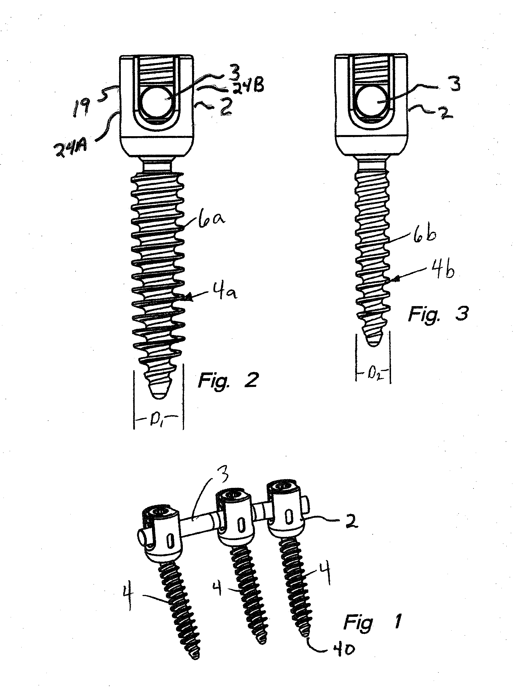
[0074]Now with reference to FIG. 1, the spinal fixation system 1 includes a plurality of polyaxial screws 4 each in cooperative relationship to a rod base member 2 for fixedly securing a stabilizing rod 3.

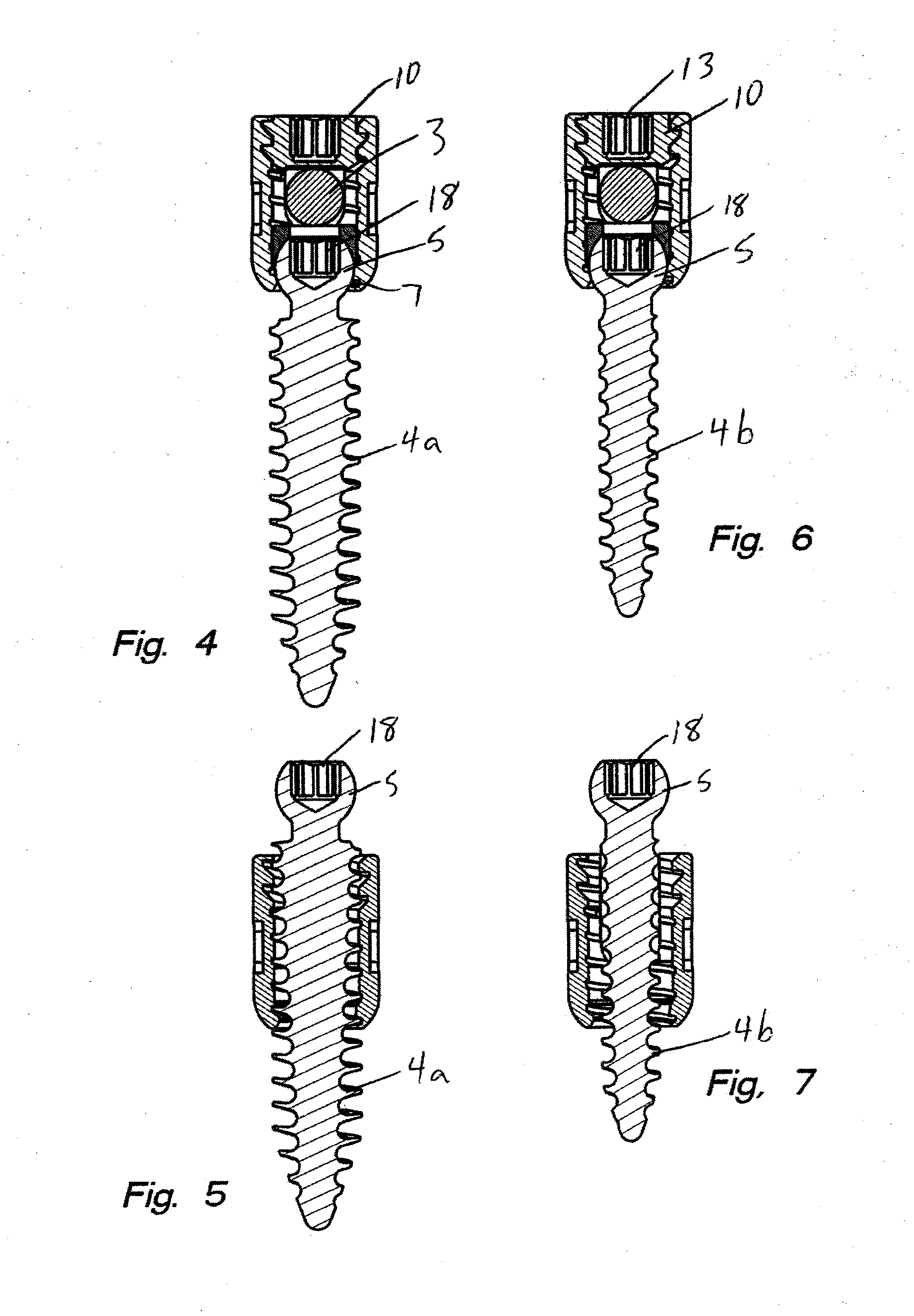
[0075]FIGS. 2 and 3, illustrate two anchoring devices wherein the diameter of the threaded shank portion 6a of the polyaxial screw 4(a) in FIG. 2 (D1) is larger than the threaded shank portion 6(b) the polyaxial screw 4(b) illustrated in FIG. 3 (D2).

[0076]FIGS. 4, 5, 6 and 7 illustrate polyaxial screws 4(a) and 4(b) each having a spherical head 5. The sphe...


PUM


Abstract

A fastening system for bone screws used in spinal fixation systems for reshaping the spine of a patient. The bone screw has threads on one end for anchoring in the spine. The other end has a spherical head with a multi sided recess formed therein for engagement with an appropriate driving tool. The system includes a stabilizing rod, a saddle member, a cap member and a set screw with at least one bone screw having a outer diameter that exceeds the diameter of a cavity formed in the saddle, wherein placement of the bone screw is made possible by matching the threads of the set screw to the threads of the bone screw. The head of the bone screw providing proper positioning of the stabilization rod within the patient.

Description

CROSS REFERENCE TO RELATED APPLICATIONS[0001]This application is a Continuation-In-Part of U.S. patent application Ser. No. 11 / 749,615, filed May 16, 2007, entitled, “Polyaxial Bone Screw”, the entire disclosure of which is incorporated herein by reference.FIELD OF THE INVENTION[0002]This invention is directed to spinal implant systems and, in particular, to a multi-component adjustable implant system and polyaxial bone screw and connector kit.BACKGROUND OF THE INVENTION[0003]For individuals with spinal pathologies, the development of spinal fixation devices represents a major medical breakthrough. Surgically implanted fixation systems are commonly used to correct a variety of back structure problems, including those which occur as a result of trauma or improper development during growth. These fixation systems typically include one or more stabilizing rods aligned in a desired orientation with respect to a patient's spine. Additionally, anchoring screws are inserted into the patien...

Claims


Application Information

Patent Timeline
IPC IPC(8): A61B17/70A61B17/86
CPCA61B17/7032A61B17/864A61B17/863A61B17/7037
Inventor DOUBLER, ROBERT L.HAMMILL, JOHN E.
Owner ORTHO INNOVATIONS
Why Eureka
Try Eureka