Vehicle Cooling System with Directed Flows

a cooling system and directed flow technology, applied in the direction of machines/engines, mechanical equipment, transportation and packaging, etc., can solve the problems of increasing the cost of manufacture, control and maintenance of pumps, and increasing the risk of failure, so as to reduce the overall coolant flow volume, reduce the cost of water pumps, and reduce the effect of overall coolant flow

Active Publication Date: 2009-12-17
HANON SYST EFP CANADA LTD
View PDF22 Cites 30 Cited by
  • Summary
  • Abstract
  • Description
  • Claims
  • Application Information

AI Technical Summary

Benefits of technology

[0012]The present invention provides an improved cooling system for internal combustion engines. The cooling system provides directed flows of heated or cooled coolant to various engine components and / or accessories as needed. By providing directed flows, the overall coolant flow volume is reduced from that of conventional cooling systems, allowing for a smaller capacity water pump to be employed which results in a net energy savings for the engine. Further, by reducing the overall coolant flow volume, the hoses and / or galleries required for the directed flows are reduced from those of conventional cooling systems, providing a cost savings and a weight savings. Finally, by preferably employing a mechanically driven impellor type water pump, the expense of an electric water pump and its associated control circuitry can be avoided. The direct flows are established by a multifunction valve which, in a preferred implementation, comprises a two-plate valve wherein each plate is operated by a wax motor, although other valve system and / or actuators, as will occur to those of skill in the art, can also be employed.

Problems solved by technology

While the cooling system taught in Henderson provides operating advantages, it still suffers from some disadvantages in that it requires an electrically operated coolant pump with a relatively high capacity to meet worst case cooling conditions.
In zero flow, or restricted flow, conditions the electric coolant pump must be electrically shut down as such pumps typically cannot be operated under zero flow conditions without damaging the pump.
Further, such pumps are more expensive to manufacture, control and maintain than are mechanical coolant pumps and can be more subject to failures.

Method used


Image

  • Vehicle Cooling System with Directed Flows
  • Vehicle Cooling System with Directed Flows
  • Vehicle Cooling System with Directed Flows

Examples


Embodiment Construction

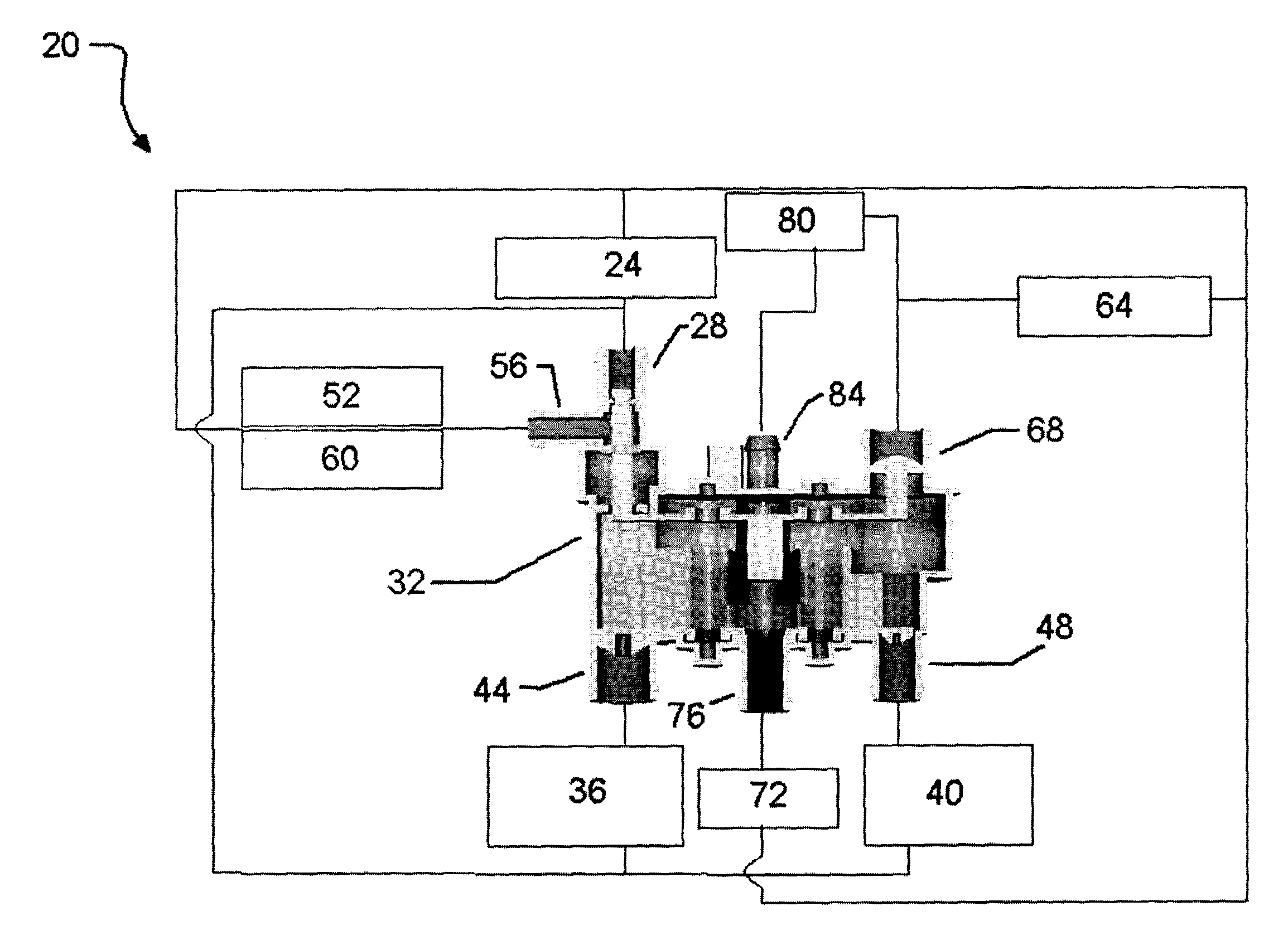
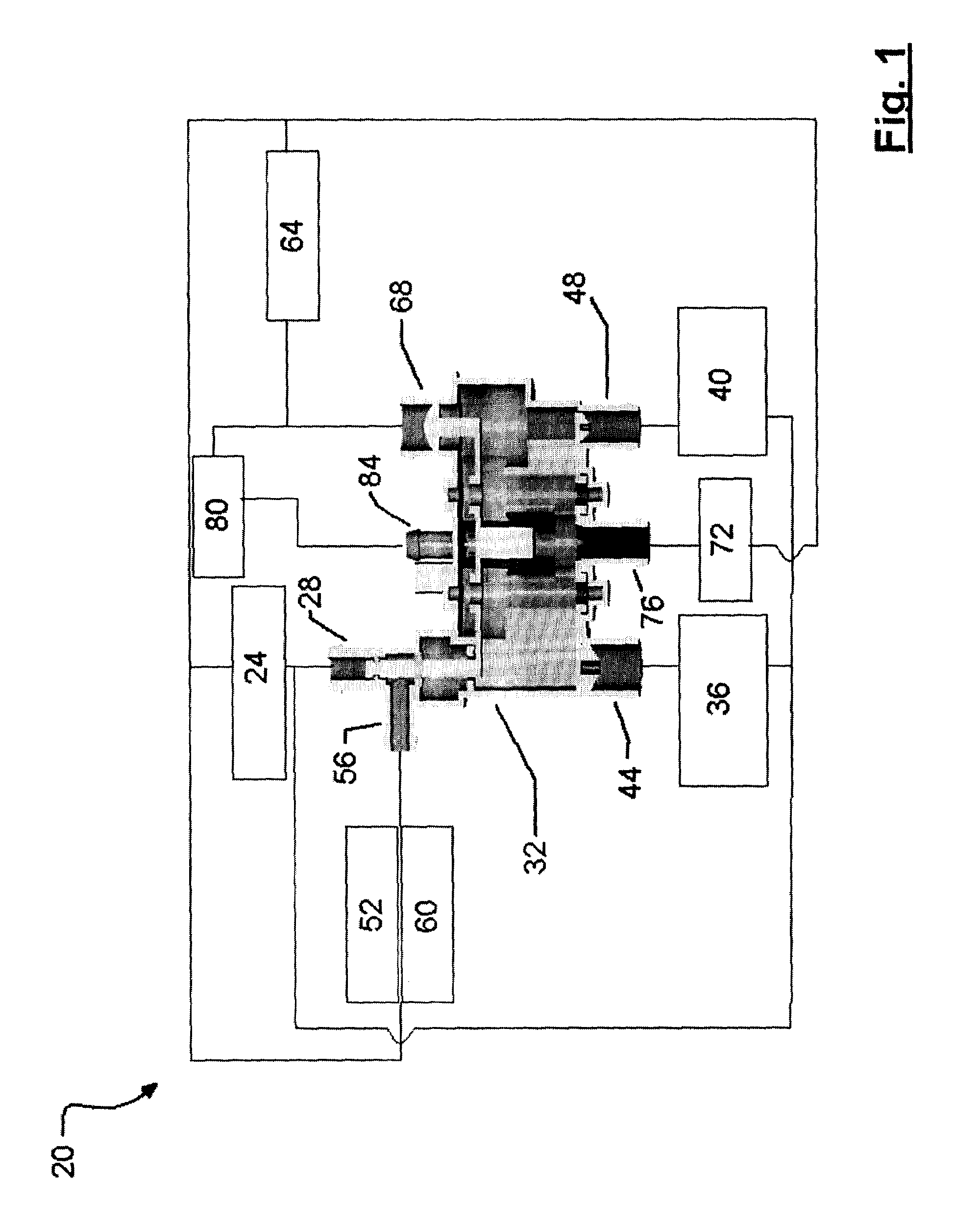
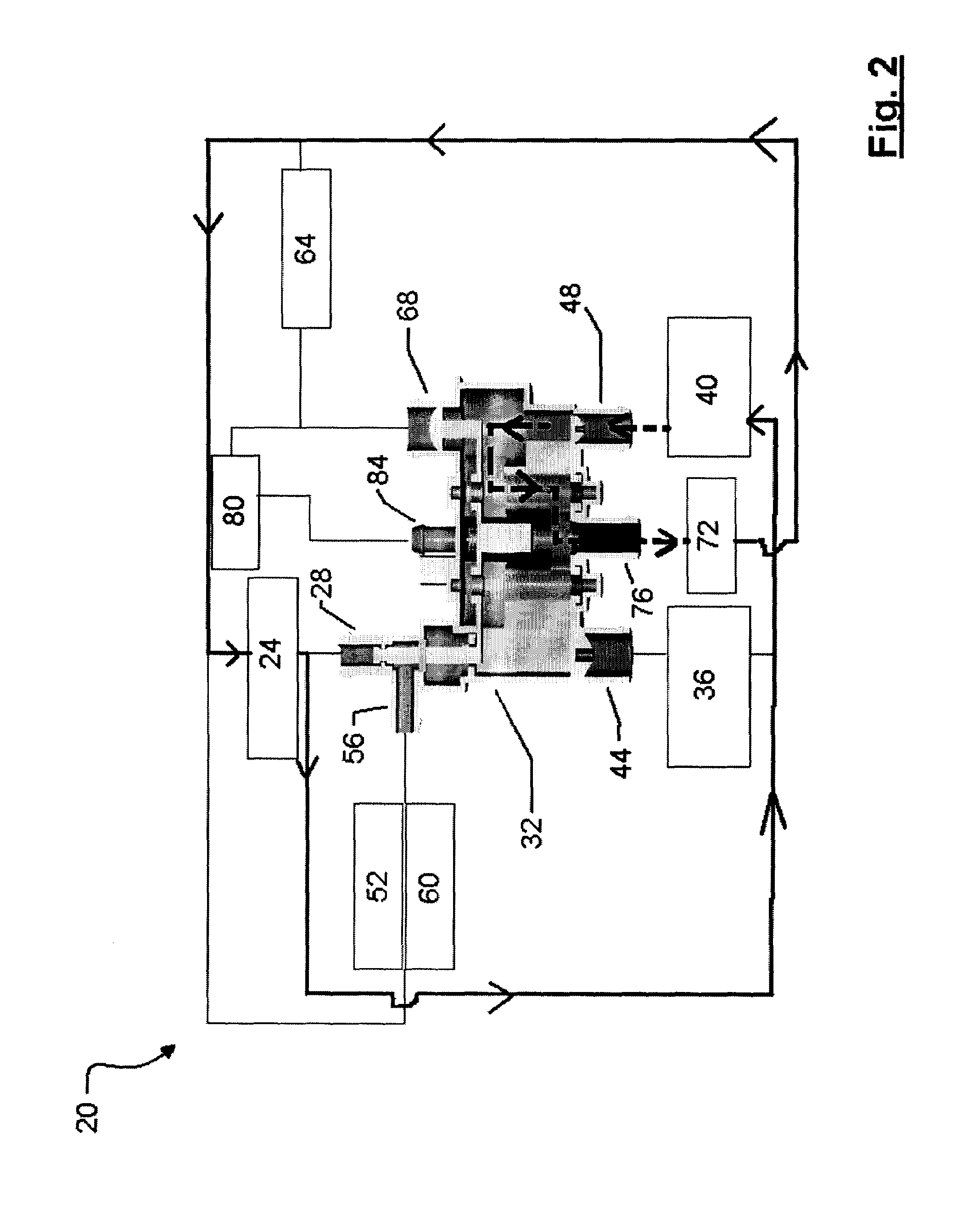
[0020]A cooling system in accordance with the present invention is indicated generally at 20 in FIGS. 1 through 6. Cooling system 20 comprises a water pump 24, which in a present embodiment of the invention is a mechanical, impeller type, water pump whose output is somewhat less than the output required from a water pump in a conventional cooling system for an equivalent sized engine. For example, if a conventional cooling system requires a water pump with an output of 4.7 litres per second at an engine speed of 7700 RPM, it is contemplated that water pump 24 can have an output of about 2.75 litres per second at 7700 RPM as with the directed flows of coolant of the present invention, as described in more detail below, a reduced flow rate (volume) of coolant can be employed, resulting in an overall energy savings for the engine with the coolant system. In the particular example discussed herein, the reduction in the required flow of coolant results in an energy savings of approximate...


PUM


Abstract

A cooling system for internal combustion engines provides directed flows of heated or cooled coolant to various engine components and / or accessories as needed. By providing directed flows, the overall coolant flow volume is reduced from that of conventional cooling systems, allowing for a smaller capacity water pump to be employed which results in a net energy savings for the engine. Further, by reducing the overall coolant flow volume, the hoses and / or galleries required for the directed flows are reduced from those of conventional cooling systems, providing a cost savings and a weight savings. Finally, by preferably employing an impellor type water pump, the expense of an electric water pump and its associated control circuitry can be avoided. The direct flows are established by a multifunction valve which, in a preferred implementation, comprises a two-plate valve wherein each plate is operated by a wax motor.

Description

FIELD OF THE INVENTION[0001]The present invention relates to cooling internal combustion engines. More specifically, the present invention relates to cooling systems for internal combustion engines in vehicles.BACKGROUND OF THE INVENTION[0002]Cooling systems for internal combustion engines in vehicles typically comprise a water jacket and various galleries in the Internal combustion engine through which coolant, typically a mixture of water and ethylene glycol, is circulated. The coolant is heated by the engine and averages temperatures in the engine (which would otherwise vary significantly from place to place) and is then passed through a heat exchanger to dissipate waste heat to the surrounding atmosphere. After rejecting some heat through the heat exchanger, the coolant is returned to the engine for another cycle.[0003]In addition to the waterjacket, galleries and heat exchanger (typically in the form of a radiator) modern cooling systems often include a variety of other compone...

Claims


Application Information

Patent Timeline
Patent Type & Authority Applications(United States)
IPC IPC(8): F01P7/14F01P5/10F02F1/10F01P11/08
CPCF01P7/165F01P11/028F01P11/08F01P7/16F01P2060/08F01P2070/04F01P2003/027Y10T137/2617F01P3/02F01P3/20F01P7/14
Inventor DIPAOLA, PASQUALECLOUGH, MALCOLM J.SCOTCHMER, ROBERT
Owner HANON SYST EFP CANADA LTD
Why Eureka
Try Eureka