Transformer and rectifier circuit using such transformer

a transformer and rectifier circuit technology, applied in the field of transformers, can solve the problems of unsatisfactory heat dissipation efficiency of the transformer, large amount of heat generated, and drawbacks of using the coil as the secondary winding assembly, and achieve the effects of reducing cost, improving heat dissipation efficiency, and small siz

Active Publication Date: 2009-12-17
DELTA ELECTRONICS INC
View PDF4 Cites 33 Cited by
  • Summary
  • Abstract
  • Description
  • Claims
  • Application Information

AI Technical Summary

Benefits of technology

[0005]It is an object of the present invention to provide a transformer having enhanced heat-dissipating efficiency, reduced cost and small size.

Problems solved by technology

Although the current-doubler rectifier circuit is effective for reducing power consumption of the DC / DC converter, there are still some drawbacks.
Since the coil is very thin, its surface area is too small and thus the heat-dissipating efficiency of the transformer is unsatisfied.
Since the rectifier circuit needs high output current, a great amount of heat will be generated during operation of the DC / DC converter.
The drawback of using the coil as the secondary winding assembly becomes more serious if the output current is increased.
This configuration results in increased size and cost.
Furthermore, since the transformer and the inductor are electrically connected with each other through designed trace patterns, the use of the trace patterns increase power loss of the current-doubler rectifier circuit.
Under this circumstance, the converting efficiency of the DC / DC converter is usually insufficient.

Method used


Image

  • Transformer and rectifier circuit using such transformer
  • Transformer and rectifier circuit using such transformer
  • Transformer and rectifier circuit using such transformer

Examples


Embodiment Construction

[0015]The present invention will now be described more specifically with reference to the following embodiments. It is to be noted that the following descriptions of preferred embodiments of this invention are presented herein for purpose of illustration and description only. It is not intended to be exhaustive or to be limited to the precise form disclosed.

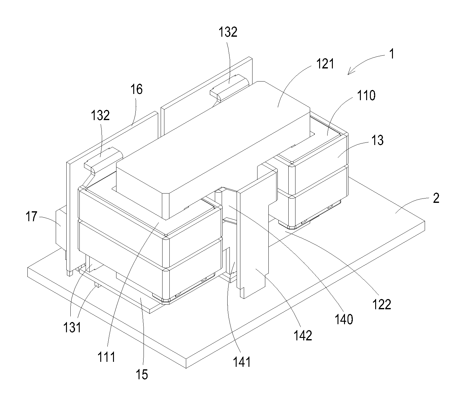
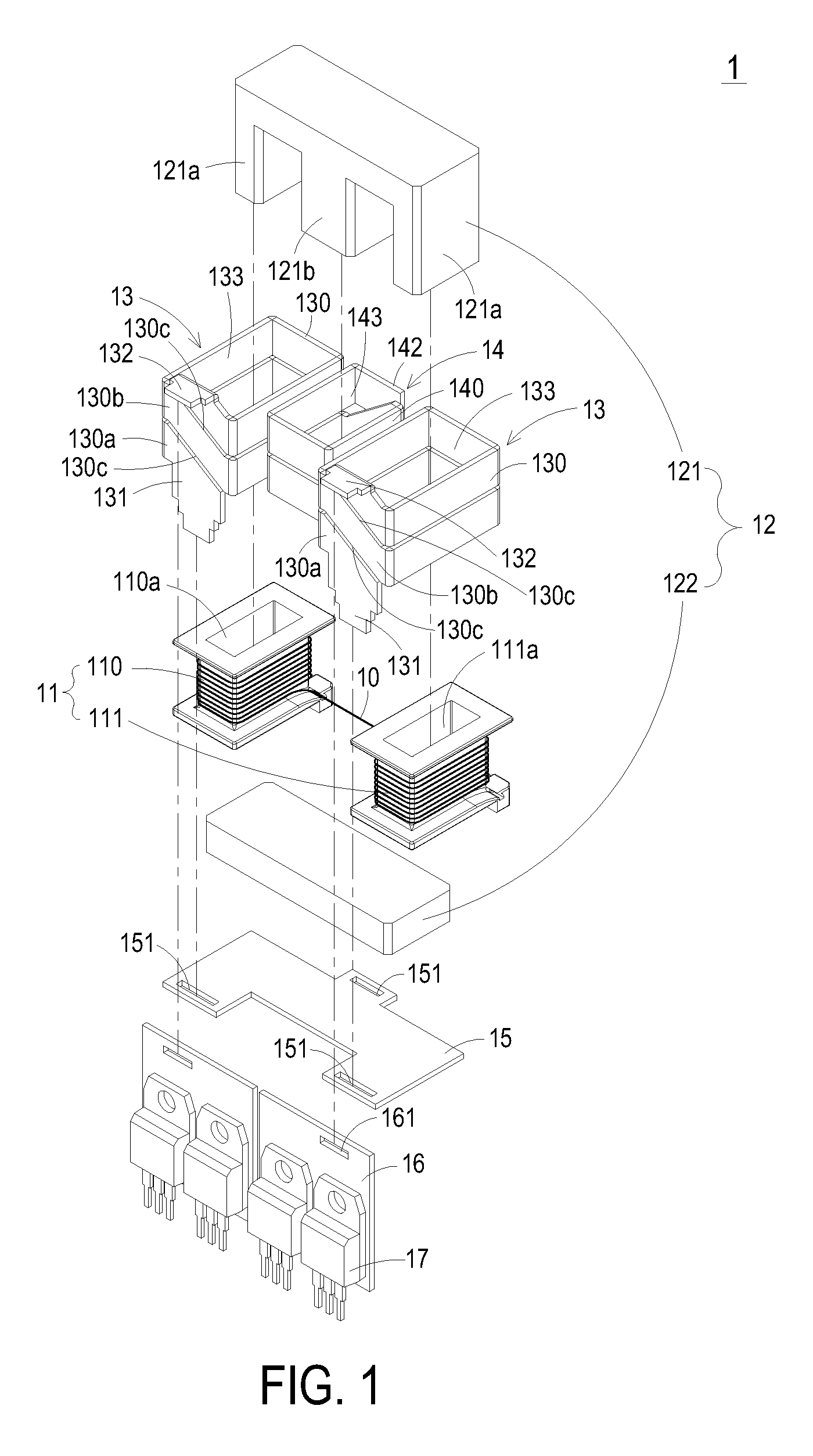
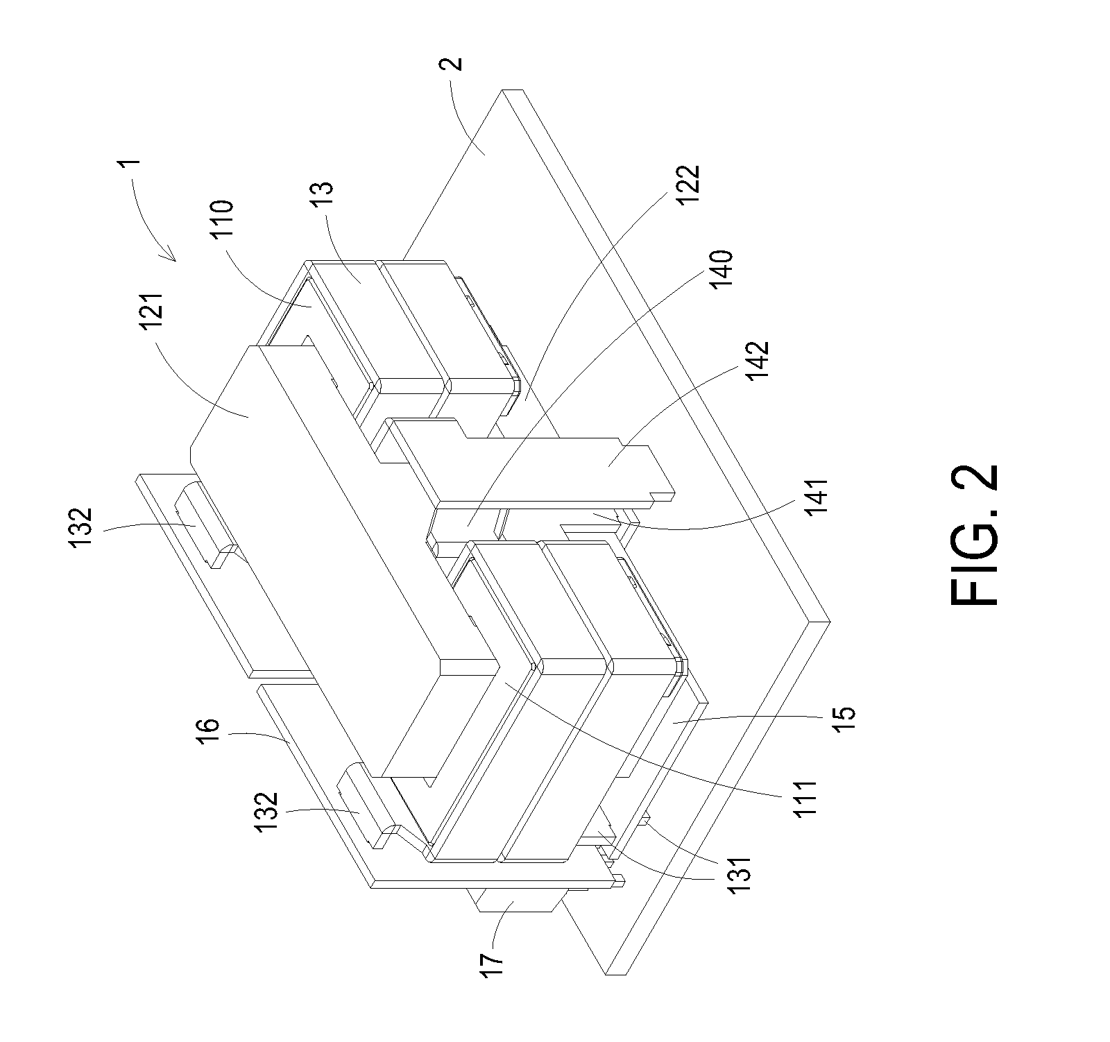
[0016]FIG. 1 is a schematic exploded view of a transformer according to a first preferred embodiment of the present invention. FIG. 2 is a schematic assembled view of the transformer of FIG. 1, which is mounted in a circuit board. Please refer to FIGS. 1 and 2. The transformer 1 of the present invention may be used in a current-doubler rectifier circuit as shown in FIG. 4. The transformer 1 principally comprises a primary winding coil 10, a winding frame member 11, a magnetic core assembly 12, multiple first three-dimensional conductive pieces 13, a second three-dimensional conductive piece 14 and a fixing plate 15. The primary w...


PUM

PropertyMeasurementUnit
conductiveaaaaaaaaaa
lengthaaaaaaaaaa
heat-dissipating efficiencyaaaaaaaaaa

Abstract

A transformer includes a primary winding coil, a winding frame member, multiple first three-dimensional conductive pieces, a second three-dimensional conductive piece, a magnetic core assembly and a fixing plate. The winding frame member includes a first winding frame and a second winding frame for winding the primary winding coil thereon. The first three-dimensional conductive pieces are respectively sheathed around the first winding frame and the second winding frame of the winding frame member. The second three-dimensional conductive piece is arranged between the first three-dimensional conductive pieces. The magnetic core assembly is partially embedded into the first three-dimensional conductive pieces, the first winding frame, the second winding frame and the second three-dimensional conductive piece. The fixing plate is connected with the first three-dimensional conductive pieces and the second three-dimensional conductive piece so as to fix the first three-dimensional conductive pieces and the second three-dimensional conductive piece.

Description

FIELD OF THE INVENTION[0001]The present invention relates to a transformer, and more particularly to a transformer having enhanced heat-dissipating efficiency, reduced cost and small size. The present invention also relates to a rectifier circuit having such a transformer.BACKGROUND OF THE INVENTION[0002]Switching power converters are used in a wide variety of applications to convert an unregulated power source into various regulated voltage levels by using several switches. For example, a switching DC / DC power converter is used to convert DC power at one voltage level into other regulated DC voltage levels. Such a switching DC / DC power converter usually has a rectifier circuit for rectifying and filtering the input power. For achieving high performance and low power consumption, the rectifier circuit with low voltage but high output current has become a potential candidate to replace the conventional rectifier circuit. For example, a well-known current-doubler rectifier (CDR) circu...

Claims


Application Information

Patent Timeline
Patent Type & Authority Applications(United States)
IPC IPC(8): H01F27/30
CPCH01F27/2866H01F27/325H02M7/003H01F27/40H01F2027/408H01F27/34
Inventor TSAI, SHENG-NANWANG, SHUN-TAITSENG, HUNG-YUTENG, CHING-HSIEN
Owner DELTA ELECTRONICS INC
Why Eureka
Try Eureka