Balloon catheter with centralized vent hole

a balloon catheter and vent hole technology, applied in the field of balloon catheters, can solve the problems of adding complexity to the procedure, affecting the effect of the patient's vasculature, and ineffective treatment of the diseased lesion, so as to minimize the misplacement of the stent, reduce the risk of stent misplacement, and limit the stent migration

Inactive Publication Date: 2009-12-17
CR BARD INC
View PDF87 Cites 18 Cited by
  • Summary
  • Abstract
  • Description
  • Claims
  • Application Information

AI Technical Summary

Benefits of technology

[0010]Applicant recognizes that it is desirable to have an apparatus and method for centrally locating the dilation balloon catheter assembly within a stenosed region to ensure proper engagement between the stenosis and the dilation balloon. The catheter assembly can be combined with a stent to form a stenosis treatment device. More specifically, the stent can be disposed about the balloon to engage the stent with a stenosis. It is desirable to have an apparatus and method for medial inflation of a dilation balloon to evenly expand the stent. Preferably, proper medial inflation and location of the dilation balloon in the stenosed region forms a “dog bone” shape. The “dog bone” shape results as the stenosis compresses evenly on the central portion of the dilated balloon and / or stent. This balloon inflation dynamic can limit stent migration along the balloon and thereby minimize any misplacement in stent deployment. Accordingly, it is desirable to provide for consistent medial inflation of the dilation balloon such that the balloon expands evenly and radially from a central point, thus avoiding uneven distortions in the dilation balloon as it is inflated.

Problems solved by technology

Stent misplacements may occur because of specific inflation dynamics experienced by the expandable balloon when deploying the stent.
End-to-end balloon inflation may further cause a deploying stent to displace longitudinally away from its intended delivery site, thereby potentially ineffectively treating the diseased lesion within the patient's vasculature.
This technique, however, adds complexity to the procedure by requiring controlled bursting or leakage of an intermediate balloon.
However, where balloons having higher operating pressures are utilized, a single lumen device may not be sufficient to provide the adequate pressure for inflating the balloon.

Method used


Image

  • Balloon catheter with centralized vent hole
  • Balloon catheter with centralized vent hole
  • Balloon catheter with centralized vent hole

Examples


Embodiment Construction

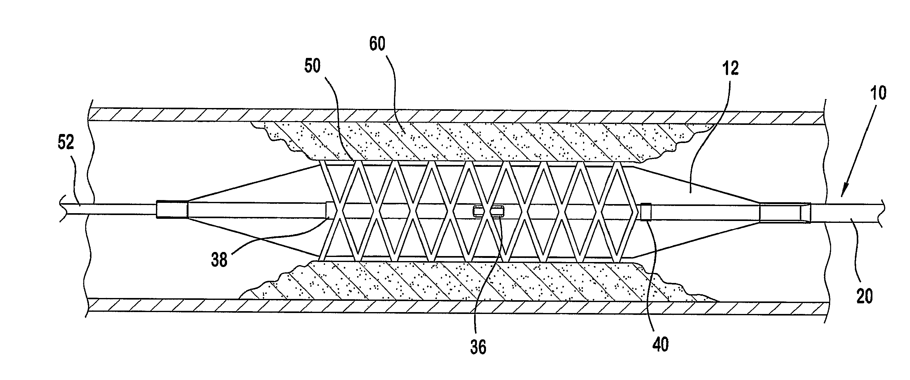
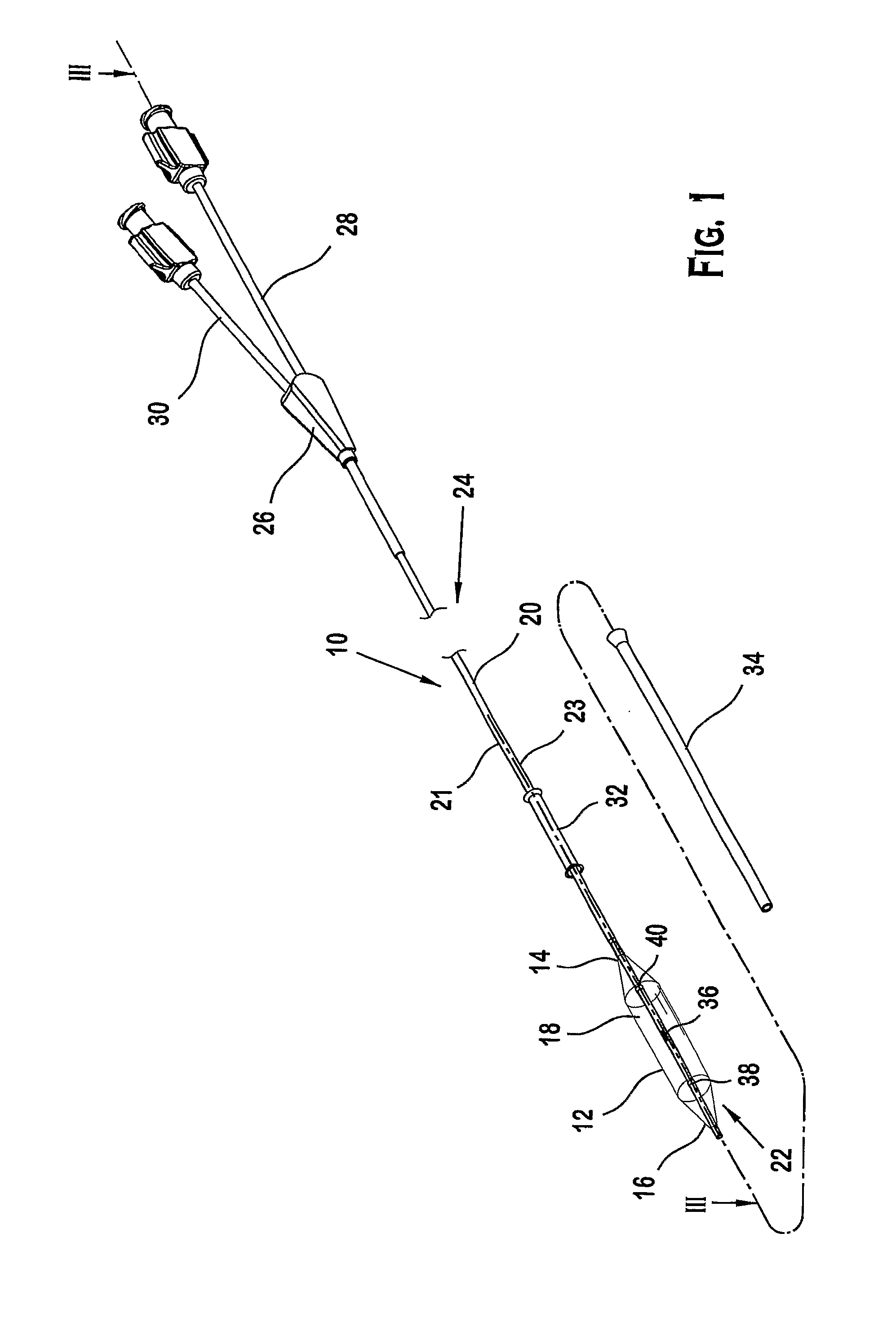
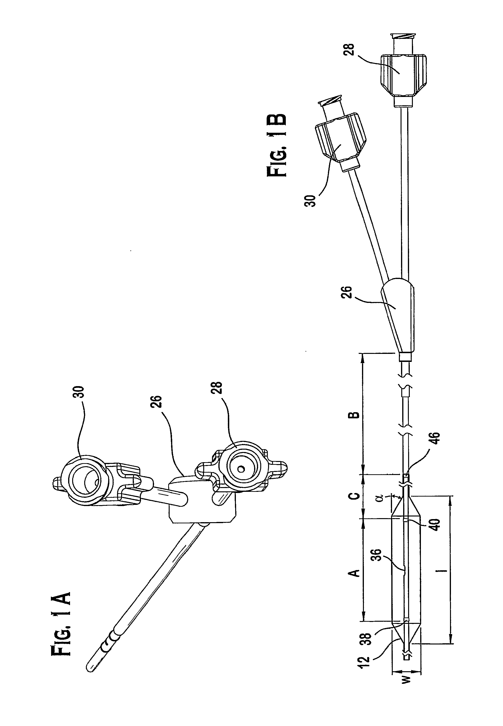
[0024]FIG. 1 shows a preferred embodiment of a catheter assembly 10 for engaging a stenosis. More specifically, the catheter assembly 10 can be configured for angioplasty procedures in which an inflatable member or balloon 12 is introduced into a blood vessel for engagement with a diseased portion of the blood vessel such as, for example, a stenosis or for engagement with an implantable prosthesis such as, for example, a stent or stent-graft. The catheter assembly 10 can be further configured for introducing an implant or stent (not shown) into the blood vessel to treat the stenosis. The stent can be disposed about the balloon 12 and the catheter assembly 10 can deliver and position the stent in engagement with the stenosis for implantation. Alternatively, the stent can be delivered to the stenosis independently of the catheter assembly 10. The catheter assembly 10 can subsequently engage the stent at the stenosis site and inflate the balloon 12 to expand the stent for engagement wi...


PUM


Abstract

A system and method providing a catheter assembly for engaging a stenosis. The assembly includes a catheter defining a first lumen and a second lumen spaced apart and disposed about a longitudinal axis. The catheter includes an opening in communication with the first lumen to define a flow path having an angle incident to the longitudinal axis. A first marker; and a second marker disposed on the catheter are spaced equidistantly from the opening. The assembly includes a balloon having a first end and a second end each sealed about the catheter and equidistantly from the opening to define a holding volume therebetween. The opening is disposed within the holding volume thereby placing the first lumen in sealed fluid communication with the holding volume. In a preferred embodiment, the catheter assembly includes a stent disposed about the balloon, and the balloon is configured to engage the stent with a stenosis.

Description

PRIORITY DATA AND INCORPORATION BY REFERENCE[0001]This application claims benefit of priority to U.S. Provisional Patent Application No. 60 / 752,878 filed Dec. 23, 2005 which is incorporated by reference in its entirety.TECHNICAL FIELD[0002]The present invention relates generally to balloon catheter assemblies for use in angioplasty and stent delivery procedures. In particular, the present invention provides a system and method for delivery of a balloon catheter to a stenosed blood vessel and inflation of the dilation balloon to expand a stent implant and / or the stenosed blood vessel.BACKGROUND ART[0003]A large number of balloon catheters have been devised for angioplasty and stent delivery procedures. Commonly a guide wire is first introduced percutaneously into the patient's vascular system, advanced and then steered to the site of a stenosis. A dilation balloon or catheter is then advanced over the guide wire until the balloon is positioned within the stenosis so that on inflation...

Claims


Application Information

Patent Timeline
Patent Type & Authority Applications(United States)
IPC IPC(8): A61F2/84A61M25/10
CPCA61M25/0108A61M25/104A61M2205/32A61M2025/1079A61M2025/1081A61M2025/1077
Inventor STAPLETON, COREY E.
Owner CR BARD INC
Why Eureka
Try Eureka