Method of Analyzing Non-Synchronous Vibrations Using a Dispersed Array Multi-Probe Machine

a multi-probe machine and dispersed array technology, applied in machines/engines, static/dynamic balance measurement, instruments, etc., can solve the problems of high installation cost, insufficient data available to provide resolution of blade vibration frequency, and typical under-sampling of blade vibration wav

Inactive Publication Date: 2009-12-24
SIEMENS ENERGY INC
View PDF19 Cites 26 Cited by
  • Summary
  • Abstract
  • Description
  • Claims
  • Application Information

AI Technical Summary

Benefits of technology

[0006]In accordance with one aspect of the invention, a method is provided for identifying an unfolded non-synchronous blade vibration frequency in blades on a rotating rotor using a plurality of sensors spaced from each other about the rotor. The method comprises the steps of acquiring a set of data from the sensors comprising measurements of blade passing events obtained during a predetermined number of rotor revolutions; processing the set of data using a Fourier analysis to generate an output representative of frequencies and phase shift angles corresponding to blade vibrations; identifying a subharmonic frequency width based on a rota

Problems solved by technology

Due to their complex design, natural resonant mechanical frequencies of the blades may coincide with or be excited by certain blade rotational speeds and rotational harmonics thereof.
While the BVM and similar systems applying Fourier analysis provide useful information for analyzing blade vibrations, the blade vibration wave is typically under-sampled, where inadequate data is available to provide resolution of the blade vibration frequencies.
However, installing additional probes is expensive and may be physically difficult to implement in that it is generally not possible to install all of the additional spaced probes at equal spacing, nor is

Method used


Image

  • Method of Analyzing Non-Synchronous Vibrations Using a Dispersed Array Multi-Probe Machine
  • Method of Analyzing Non-Synchronous Vibrations Using a Dispersed Array Multi-Probe Machine
  • Method of Analyzing Non-Synchronous Vibrations Using a Dispersed Array Multi-Probe Machine

Examples


Embodiment Construction

[0018]In the following detailed description of the preferred embodiment, reference is made to the accompanying drawings that form a part hereof and in which is shown by way of illustration, and not by way of limitation, a specific preferred embodiment in which the invention may be practiced. It is to be understood that other embodiments may be utilized and that changes may be made without departing from the spirit and scope of the present invention.

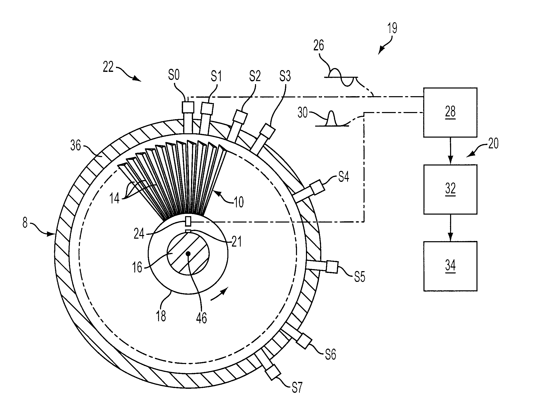
[0019]FIG. 1 diagrammatically illustrates a turbo-machine 8, such as a turbine, including a shrouded turbine blade row 10 in which the method of the present invention can be employed in a blade vibration monitoring system to monitor non-synchronous turbine blade vibrations. Turbine blades 14 are connected to a rotor 16 by means of a rotor disk 18. Although the illustrated embodiment references non-shrouded blades 14, it should be understood that the present invention is equally applicable to analyze shrouded blades.

[0020]Also shown in FIG...


PUM


Abstract

A method for identifying an unfolded non-synchronous blade vibration frequency in blades on a rotating rotor using a plurality of probes spaced from each other about the rotor. A set of data is acquired from the probes during a predetermined number of rotor revolutions and is processed using a Fourier analysis to generate an output representative of frequencies and phase shift angles corresponding to blade vibrations. The phase shift angles are used to identify a subharmonic for a blade vibration frequency to provide an output identifying the vibration frequency. A space dispersion and time dispersion of probes is described to increase the accuracy of the subharmonic determination using the phase shift angles.

Description

FIELD OF THE INVENTION[0001]The present invention relates to monitoring the vibrational characteristics of a rotating blade row and, more particularly, to a method of analyzing non-synchronous vibrations detected by a multi-probe machine.BACKGROUND OF THE INVENTION[0002]A high speed turbo machine, such as, for example, a steam or gas turbine, generally comprises a plurality of blades arranged in axially oriented rows, the rows of blades being rotated in response to the force of a high pressure fluid flowing axially through the machine. Due to their complex design, natural resonant mechanical frequencies of the blades may coincide with or be excited by certain blade rotational speeds and rotational harmonics thereof. To prevent excessive vibration of the blade about its normal position, prudent design practice dictates that the blades be constructed such that the frequencies of the lowest modes fall between harmonics of the operating frequency of the turbine. In addition, the blades ...

Claims


Application Information

Patent Timeline
IPC IPC(8): G01H1/00G01B7/14
CPCG01H1/006
Inventor TWERDOCHLIB, MICHAEL
Owner SIEMENS ENERGY INC
Why Eureka
Try Eureka