Radiofrequency identification device and method for producing said device

a radiofrequency identification and tag technology, applied in the direction of instruments, electrical equipment, antennas, etc., can solve the problems of chip damage, affecting the proper functioning of the tag, and the tag b>100/b> affixed to the support b>101/b> may become unstuck, so as to improve the strength of the assembly

Inactive Publication Date: 2009-12-24
ID3S IDENTIFICATION SOLUTIONS SYST & SERVICES
View PDF7 Cites 33 Cited by
  • Summary
  • Abstract
  • Description
  • Claims
  • Application Information

AI Technical Summary

Benefits of technology

[0013]Due to the intermediate layer protecting the antenna, affixing the RFID device to a metal object does not impair the transmission of the information contained in the chip.
[0014]In addition, providing a cavity in the intermediate layer in order to house the potting has many advantages:
[0015]the increase in the total thickness of the RFID device due to the presence of the intermediate layer is limited and at least partly compensated for by the fact that the thickness of the potting does not add to the thickness of the other constitutive layers of the RFID. The RFID device is therefore not very thick, despite the intermediate layer. Thus, in particular when the RFID device forms a tag, and depending on the materials used, it may have a rigidity sufficiently low to be able to be bent and affixed to a warped support. In addition, once affixed to the support, the RFID device offers little grip and there is therefore less risk of it being torn off from the support;
[0016]there is no longer additional thickness of the RFID device level with the chip, and the visible face of the RFID device therefore does not comprise a boss. This makes it possible to produce very high quality printing on this face. In addition, the resistance of the RFID device to being torn off is reduced considerably by eliminating the localized boss of the prior art; and
[0024]Advantageously, the antenna forms a ring and the intermediate layer comprises a through hole positioned facing a through hole formed in the central area formed by the antenna. This makes it possible to create an additional adhesive area between the part of the envelope situated on the side of the substrate and the part of the envelope situated on the side of the intermediate layer, which improves the strength of the assembly.

Problems solved by technology

As a consequence, on the one hand, the production of the envelope 107, for example by lamination, may lead to damage to the chip 105 and impair proper functioning of the tag.
Due to this, there is a risk that the tag 100 affixed to the support 101 may become unstuck when a person or an object bumps into the boss 109.
This may even lead to problems reading this information.
Another drawback of known RFID devices is that they cannot be affixed to a metal support or used in close proximity to a metal object, as the metal prevents correct transmission of the information contained in the chip by means of the antenna.
Furthermore, the rigidity of most known RFID tags is too high, which means that these tags cannot be located on warped supports.

Method used


Image

  • Radiofrequency identification device and method for producing said device
  • Radiofrequency identification device and method for producing said device
  • Radiofrequency identification device and method for producing said device

Examples


first embodiment

[0058] the tag 1 is produced by lamination.

second embodiment

[0059] the tag 1 is produced by moulding. It may be injection moulding, moulding by gravity casting, at ambient temperature or with heating.

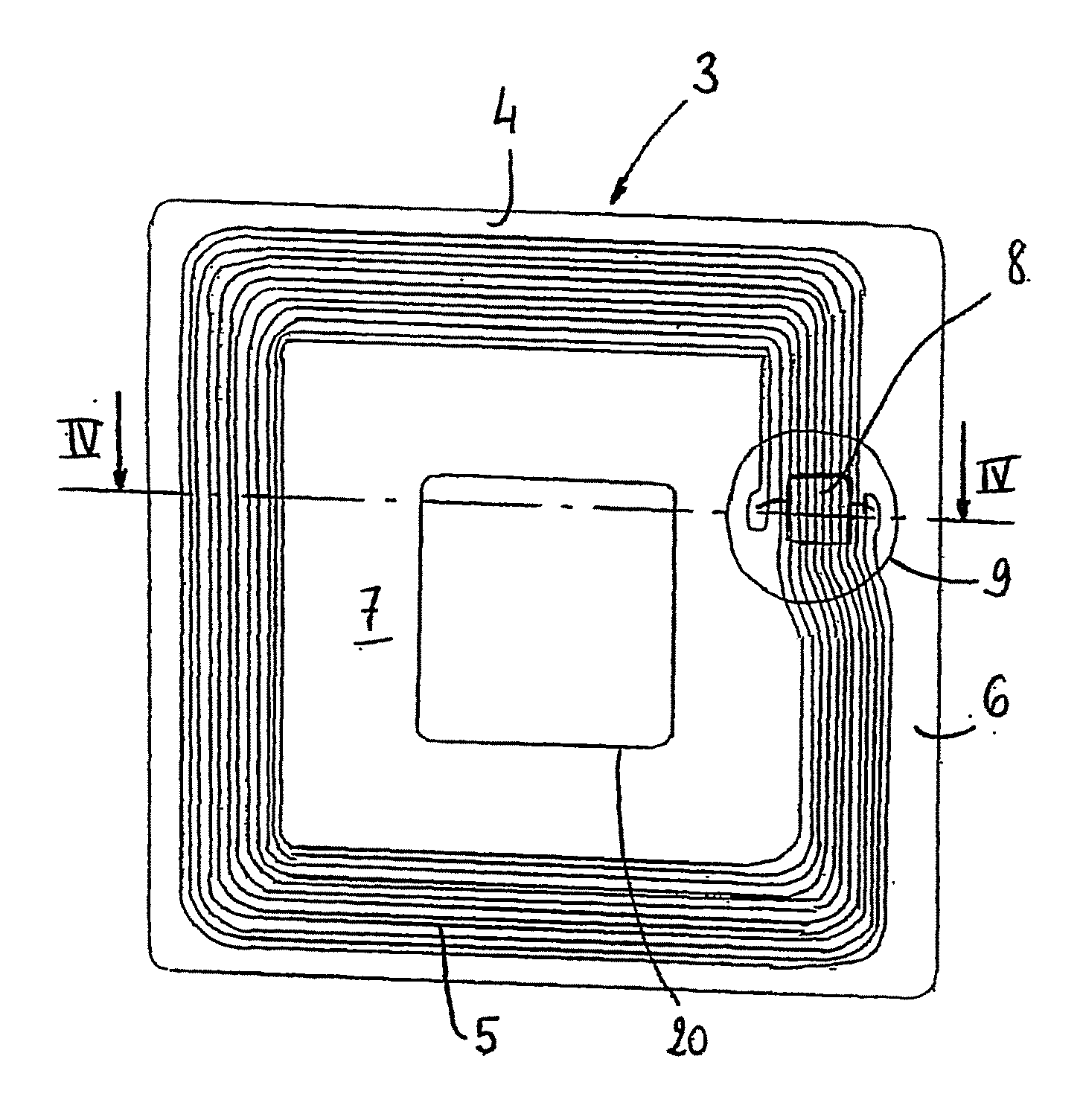
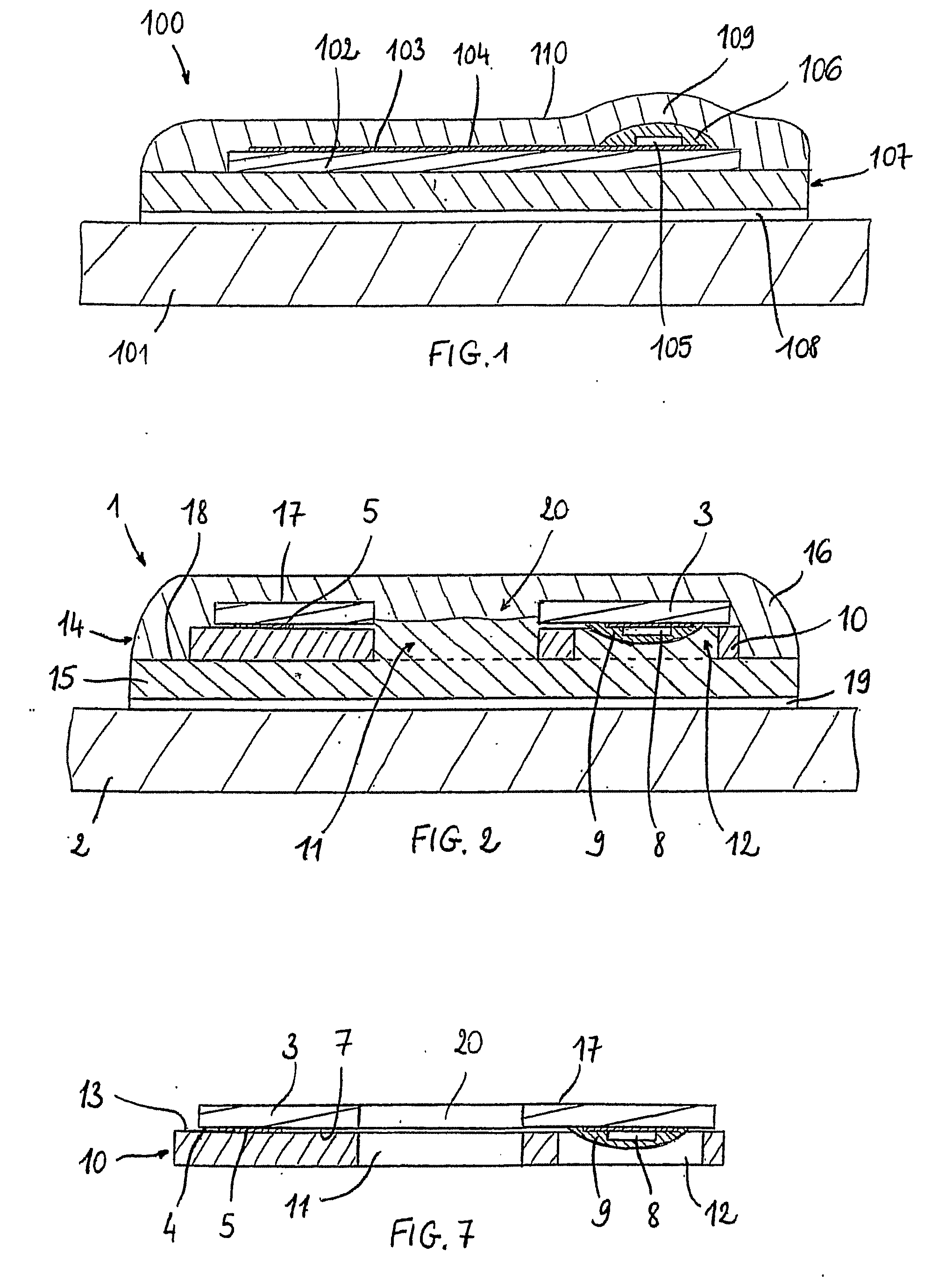
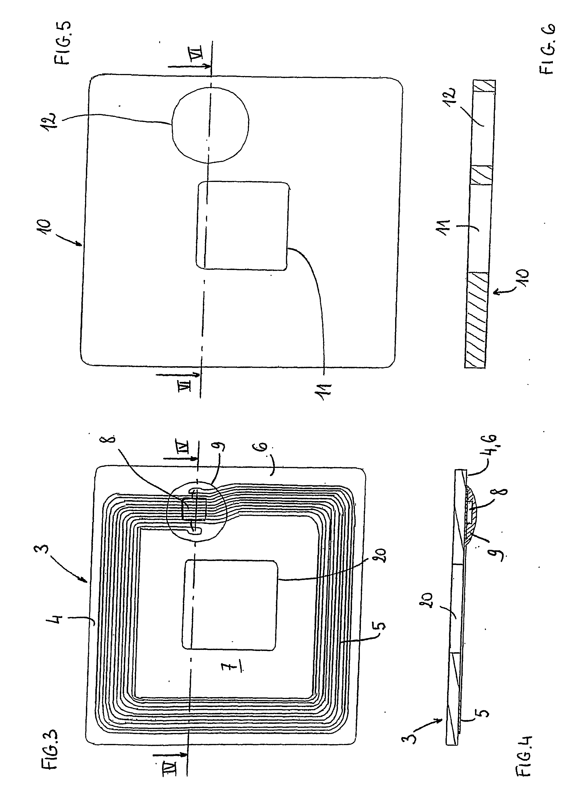
[0060]Whatever embodiment is adopted, in the course of forming the tag 1, on the one hand, the first layer 15 of the envelope 14 penetrates the orifice 12, thus embedding the potting 9. It should be noted that this does not cause a localized lack of thickness in the tag 1. On the other hand, the layers 15, 16 of the envelope 14 penetrate the through holes 11, 20, which enables good adhesion of these layers to one another.

[0061]Although the envelope 14 has been presented as consisting of two distinct layers 15, 16 (which is the case in particular for lamination), the envelope 14 may also be formed of only a single piece (for example if it is obtained by moulding).

[0062]The tag 1 may finally comprise an adhesive layer 19 joined to the first layer 15 of the envelope 14. The adhesive layer 19 has, for example, a thickness close to 170 μm.

[0063]The t...


PUM

PropertyMeasurementUnit
thicknessaaaaaaaaaa
thicknessaaaaaaaaaa
diameteraaaaaaaaaa

Abstract

“The radio-frequency identification device includes embedded in an envelope a substrate on one face of which an antenna is produced and a chip connected to the antenna is positioned, a potting locally covering the substrate face level with the chip, an intermediate layer made of a magnetic superconductor material placed against the substrate on the antenna side, the intermediate layer having dimensions greater than those of the antenna so as to be able to cover the antenna and having a cavity arranged so that the potting and the chip can be approximately completely housed therein.”

Description

TECHNICAL FIELD OF THE INVENTION[0001]The present invention relates to a radio-frequency identification device and a method for producing such a device.[0002]BRIEF DISCUSSION OF RELATED ART[0003]Radio-frequency identification devices (RFID devices) make it possible to identify objects by using an electronic device—such as a memory chip—containing data and capable of transmitting information to a dedicated reader using an antenna. An identification tag or a contactless payment card are examples of such RFID devices.[0004]FIG. 1 shows a sectional view of an RFID tag 100 of the prior art affixed to a support 101. The tag 100 comprises a substrate 102, on one face 103 of which an antenna 104 is produced and a chip 105, connected to the antenna 104, is positioned. In addition, a potting 106 locally covers this face 103 of the substrate 102 level with the chip 105. The assembly formed from the substrate 102, the antenna 104, the chip 105 and the potting 106 is enclosed by an envelope 107....

Claims


Application Information

Patent Timeline
Patent Type & Authority Applications(United States)
IPC IPC(8): G06K19/077H01L21/50
CPCG06K19/07798G06K19/07771Y10T29/49018G06K19/0776G06K19/07749
Inventor CHARRIN, PHILIPPE
Owner ID3S IDENTIFICATION SOLUTIONS SYST & SERVICES
Why Eureka
Try Eureka