Output current detection of a voltage regulator

a voltage regulator and output current technology, applied in the field of voltage regulators, can solve the problems of small voltage variation, easy interference, small voltage variation, etc., and achieve the effect of facilitating the feedback control of the voltage regulator, preventing efficiency loss, and precise detection of variation

Inactive Publication Date: 2009-12-24
RICHTEK TECH
View PDF4 Cites 23 Cited by
  • Summary
  • Abstract
  • Description
  • Claims
  • Application Information

AI Technical Summary

Benefits of technology

[0009]The present invention proposes an apparatus and method for output current detection of a voltage regulator, which remove the current sensing resistor from the charging current path of the voltage regulator to prevent the efficiency loss on it, and enable precise detection of the variation at the output of the voltage regulator by using the setting resistor not in the charging current path for facilitating the feedback control of the voltage regulator.

Problems solved by technology

But this current sensing resistor will reduce the efficiency and may cause thermal issue.
However, a low resistance can produce only a small voltage variation and a small voltage variation is sensitive to and easily interfered by noise.

Method used


Image

  • Output current detection of a voltage regulator
  • Output current detection of a voltage regulator
  • Output current detection of a voltage regulator

Examples


first embodiment

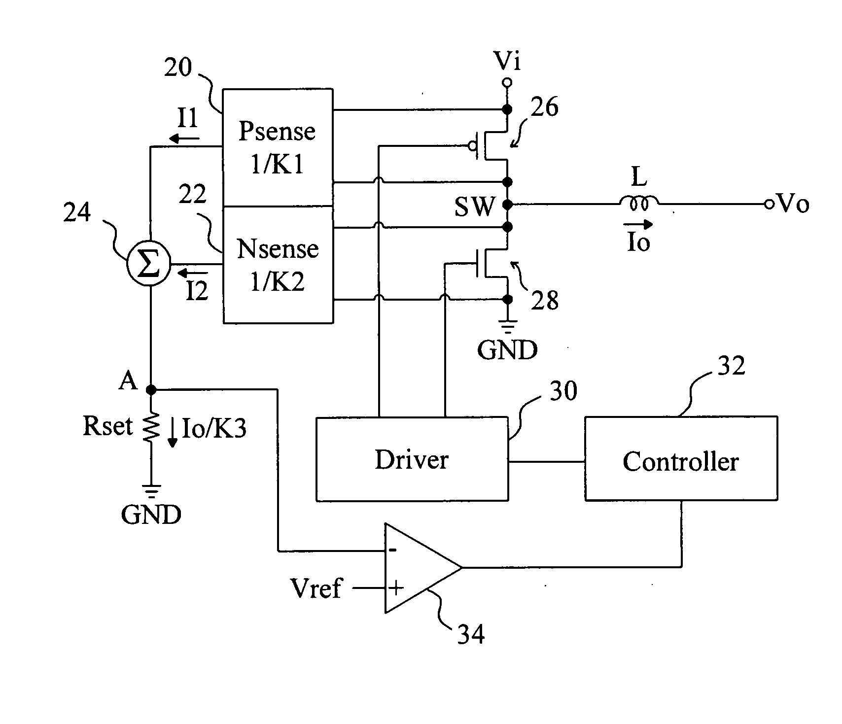
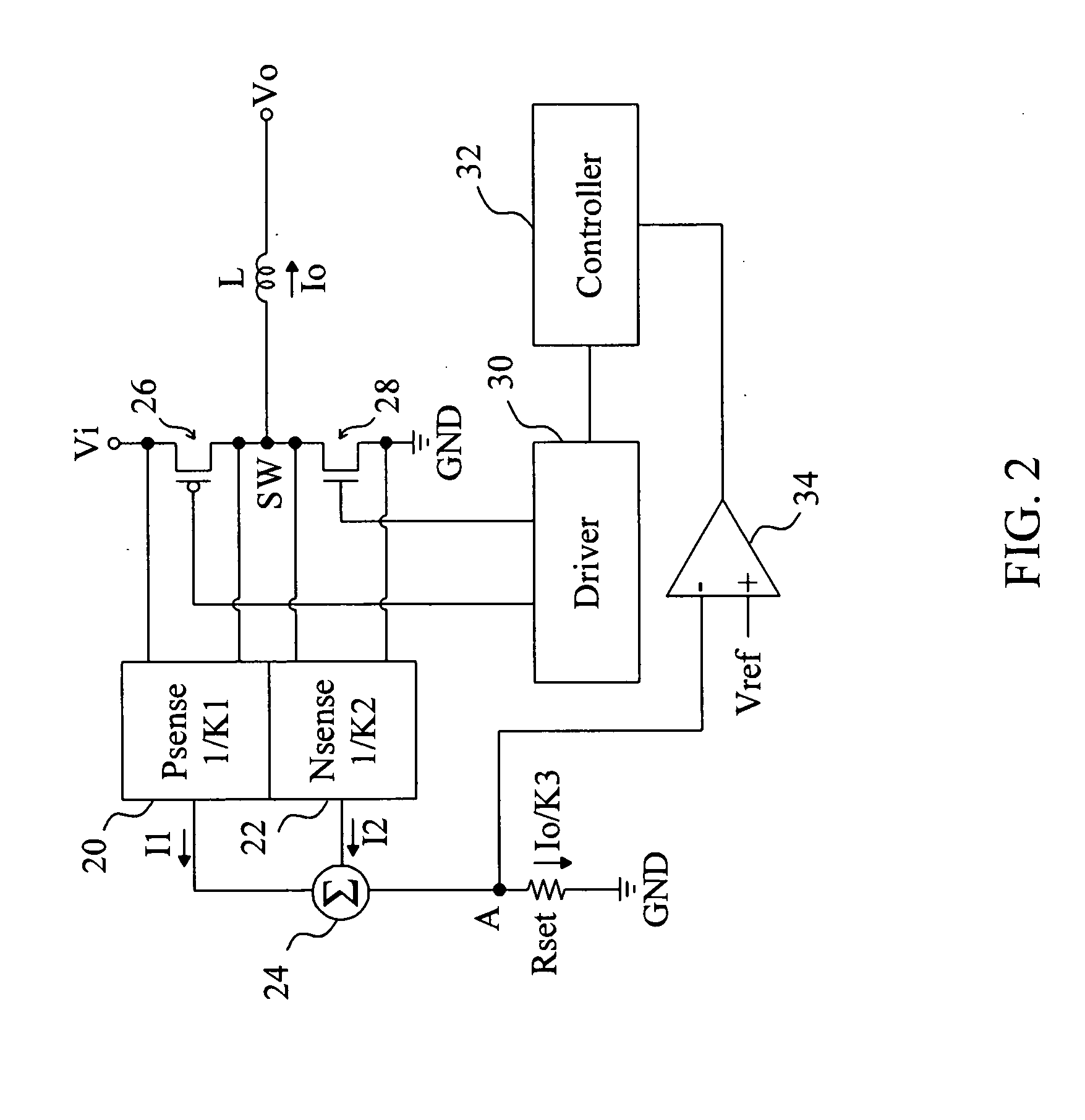
[0017]FIG. 2 provides a first embodiment according to the present invention for buck voltage regulators, in which a high-side transistor 26 is coupled between a power input Vi and a switching node SW, a low-side transistor 28 is coupled between the switching node SW and a ground terminal GND, an inductor L is coupled between the switching node SW and a power output Vo, a driver 30 switches the high-side transistor 26 and the low-side transistor 28 to control the output current Io flowing through the inductor L to generate an output voltage Vo, a high-side sensing circuit 20 senses the current in the high-side transistor 26 to generate a current I1 with K1 ratio, a low-side sensing circuit 22 senses the current in the low-side transistor 28 to generate a current I2 with K2 ratio, and the currents I1 and I2 are summarized by a summing circuit 24 to flow through a setting resistor Rset. The role of the setting resistor Rset is similar to the conventional current sensing resistor Rsense...

second embodiment

[0020]FIG. 4 provides a second embodiment according to the present invention, which uses an apparatus for output current detection of a non-synchronous buck voltage converter having a diode D as the low-side element. In this embodiment, instead of detecting the current in the diode D, the sensing circuit 42 only senses the current in the high-side transistor 40, and a current Is having the waveform shown at the lower part of FIG. 3 is produced by a simulation circuit 44 to provide to the setting resistor Rset to generate a voltage thereon for feedback control (not shown in FIG. 4). In another embodiment, the aforesaid current simulation is replaced by directly detecting the current in the diode D to be combined with the current in the high-side transistor 40 to supply to the setting resistor Rset.

third embodiment

[0021]FIG. 5 is a diagram of a third embodiment according to the present invention for boost voltage regulators, in which a sensing circuit 56 senses the current in a high-side transistor 54 to generate a current I1, a sensing circuit 58 senses the current in a low-side transistor 52 to generate a current I2, and the currents I1 and I2 are summarized by a summing circuit 60 to generate a sensing current Is to flow through a setting resistor Rset to produce a voltage at a node B to be monitored by a comparator 66 to provide a feedback signal to a controller 64 for feedback control. A driver 62 generates driving signals to switch the high-side and low-side transistors 54, 52 under the control of the controller 64. In this embodiment, the proportion between the currents I1 and I2 is also adjustable, for example, by using different parameters K4 and K5.

[0022]FIG. 6 is a diagram of a modified embodiment from that of FIG. 5. In this embodiment, the inverse of K5 is set to be zero. Namely,...


PUM


Abstract

For output current detection of a voltage regulator, the currents in a high-side transistor and a low-side transistor of the voltage regulator are sensed and summarized to a summed current to flow through a setting resistor. The voltage variation on the setting resistor is monitored to provide a feedback signal for feedback control in the voltage regulator. This detection scheme removes the current sensing resistor from the charging current path of the voltage regulator to prevent efficiency loss on it, and is much less sensitive to noise interference because greater voltage variation is available by using a greater setting resistor.

Description

FIELD OF THE INVENTION[0001]The present invention is related generally to voltage regulators and, more particularly, to the output current detection of a voltage regulator.BACKGROUND OF THE INVENTION[0002]To provide a regulated output current as a charger from a buck-type converter, typically a current sensing resistor is connected to the inductor to detect the current flowing therethrough by monitoring the dropout voltage on the current sensing resistor. But this current sensing resistor will reduce the efficiency and may cause thermal issue. For example, FIG. 1 is a diagram showing a popular structure in switching chargers by using a current sensing resistor, as disclosed in U.S. Pat. No. 6,369,561, LTC 4001 and SMB 135, in which the output current Io of a voltage regulator flows through a current sensing resistor Rsense so that the voltage drop on the current sensing resistor Rsense is proportional to the output current Io and, more specifically, the current flowing through the c...

Claims


Application Information

Patent Timeline
Patent Type & Authority Applications(United States)
IPC IPC(8): G05F1/10
CPCH02M2001/0009H02M3/158H02M1/0009
Inventor KUNG, NIEN-HUICHU, KWAN-JEN
Owner RICHTEK TECH
Why Eureka
Try Eureka