Determining in-band optical signal-to-noise ratios in optical signals with time-varying polarization states using polarization extinction

a technology of polarization extinction and optical signal, which is applied in the direction of optical radiation measurement, electromagnetic transmission, instruments, etc., can solve the problems of large potential, difficult to measure the optical noise floor between adjacent signals in the received optical spectrum, and the degraded signals transmitted over long-distance fiber-optic communication systems. , to achieve the effect of limiting the degradation of the calculated polarization extinction ratio

Active Publication Date: 2009-12-24
VIAVI SOLUTIONS INC
View PDF6 Cites 21 Cited by
  • Summary
  • Abstract
  • Description
  • Claims
  • Application Information

AI Technical Summary

Benefits of technology

[0018]wherein the measurement time in step (d) is sufficiently short so that the polarization state of the optical light signal in the selected wavelength channel is substantially constant during the measurement of the optical power, thereby limiting a degradation in the calculated polarization extinction ratio.

Problems solved by technology

Signals transmitted over long-distance fiber-optic communication systems may be severely degraded by excessive optical noise, which is introduced by optical amplifiers employed to boost signal power throughout each system.
In modern optical transmission systems with wavelength multiplexing, the various transmitted signals may be closely spaced in optical frequency, thus making it very difficult to measure the optical noise floor between adjacent signals in the received optical spectrum.
However, it is well known to those skilled in the art that the output polarization state of a signal transmitted over an optical fiber may fluctuate randomly with time, because standard optical fibers do not maintain the state of polarization of the launched signals.
The speed and magnitude of the polarization fluctuations introduced in the fiber depend on the physical environment to which the fiber is exposed, and therefore, may be potentially large.
Consequently, these random polarization fluctuations may severely limit in-band OSNR measurements using the polarization-extinction method or other types of polarization analysis.
Therefore, polarization fluctuations in the optical information signal may severely degrade in-band OSNR measurements that are obtained by polarization analysis.

Method used


Image

  • Determining in-band optical signal-to-noise ratios in optical signals with time-varying polarization states using polarization extinction
  • Determining in-band optical signal-to-noise ratios in optical signals with time-varying polarization states using polarization extinction
  • Determining in-band optical signal-to-noise ratios in optical signals with time-varying polarization states using polarization extinction

Examples


Embodiment Construction

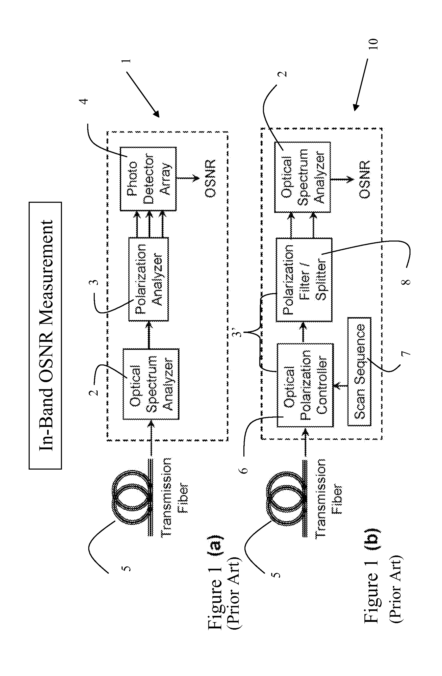
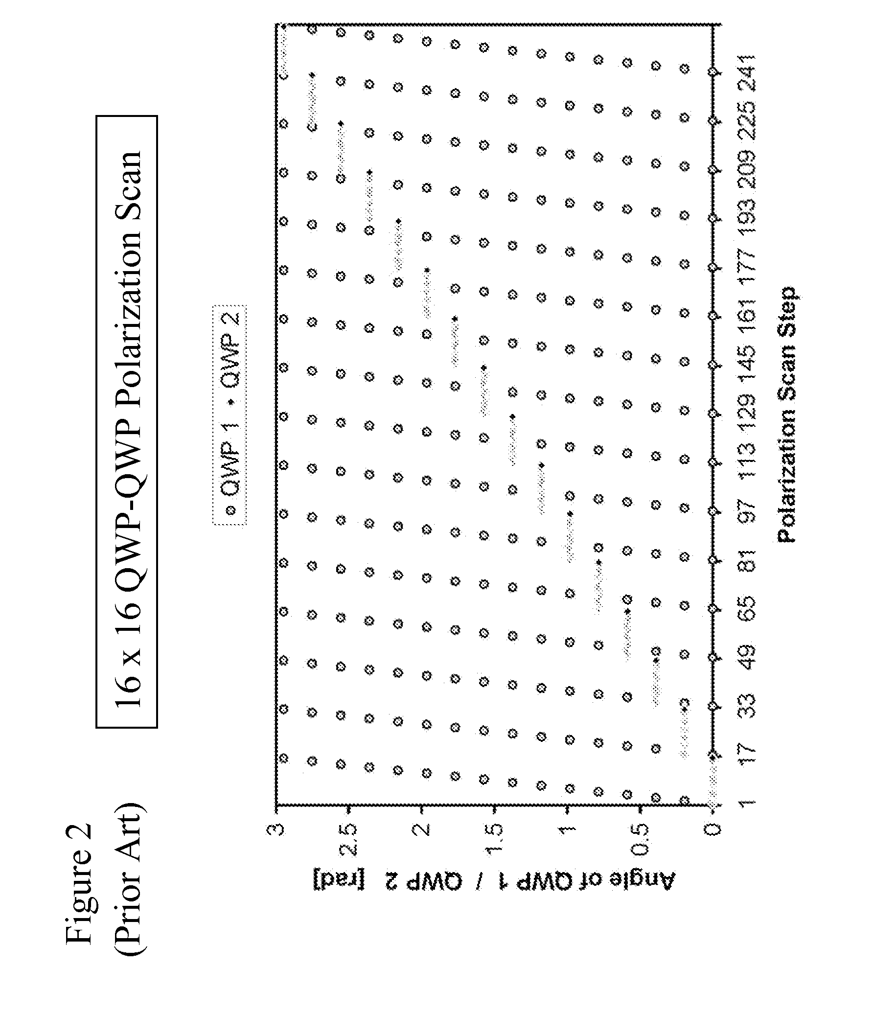
[0044]Polarization controllers for transforming a given input polarization state into a multitude of output polarizations states normally are composed of several elements or stages, whereby each stage changes the state of polarization in a substantially different way. An exemplary embodiment of a polarization controller comprises a combination cascade of two optical wave plates at variable angular orientation, which may be composed of two rotatable quarter-wave plates (QWPs), as illustrated for example in FIG. 7(b), or of a QWP and a half-wave plate (HWP). The wave plates may be rotated mechanically or by means of a electro- or magneto-optic effect. To generate a suitable sequence of substantially different polarization states, the angular orientation of these wave plates may be adjusted in a number of predetermined steps and in a systematic fashion. In the above example, in which the polarization controller is comprised of two cascaded QWPs, the angle of each QWP may be varied in a...


PUM


Abstract

A method and apparatus for improving the accuracy of in-band OSNR measurements using a conventional polarization extinction or polarization-nulling method. In particular, the severe degradations of the polarization extinction that result from slow and fast polarization fluctuations in the optical signal components during the in-band OSNR measurement are substantially mitigated by rapidly and / or randomly changing the state of polarization prior to conventional polarization control and filtering.

Description

CROSS-REFERENCE TO RELATED APPLICATIONS[0001]The present invention claims priority from U.S. Patent Application No. 61 / 073,988 filed Jun. 19, 2008, which is incorporated herein by reference.TECHNICAL FIELD[0002]The present invention relates to the determination of optical signal-to-noise ratios, and in particular to the use of polarization extinction to determine in-band optical signal-to-noise ratios (OSNR) in optical signals that exhibit slow or rapid variations in the state of polarization.BACKGROUND OF THE INVENTION[0003]Signals transmitted over long-distance fiber-optic communication systems may be severely degraded by excessive optical noise, which is introduced by optical amplifiers employed to boost signal power throughout each system. The quality of a transmitted optical signal, therefore, is frequently characterized by the optical signal-to-noise ratio (OSNR), which defines the ratio of the signal power carrying the desired information signal and the optical noise added in...

Claims


Application Information

Patent Timeline
Patent Type & Authority Applications(United States)
IPC IPC(8): G01J4/00
CPCH04B10/07953
Inventor HEISMANN, FRED L.
Owner VIAVI SOLUTIONS INC
Why Eureka
Try Eureka