
Workpiece transportation system comprising automated transport vehicles and workpiece carriers

a technology for workpieces and carriers, applied in the field of transportation systems, can solve the problems of complex line structure, insufficient creation of control programs for such parts, imperfect and insufficient transportation equipment disclosed, etc., and achieve the effects of improving usability, convenient creation and change, and efficient circulation of carriers

Inactive Publication Date: 2009-12-24
YAZAKI IND CHEM CO LTD
View PDF11 Cites 3 Cited by
  • Summary
  • Abstract
  • Description
  • Claims
  • Application Information

AI Technical Summary

Benefits of technology

[0013]The primary object of the present invention is to provide a workpiece transportation system wherein a supply-side line and a consumption-side line is connected by a buffer line in a simple structure, the buffer line including an outward line section corresponding to the above-mentioned storage line on which workpiece carriers that have been loaded with workpieces in a supply-side area and traveled along the supply-side line temporarily wait, and a homeward line section on which workpiece carriers that have been emptied by consuming or unloading workpieces in a consumption-side area and brought back along the consumption-side line (empty carriers) temporarily wait; and wherein the need of at least such route switch means and propulsion means as in the prior art is obviated and all the actions can be carried out by the automated function of automated transport vehicles, so that control programs required are easy to create, change of a guideway can be carried out in large part by standardized work, and adaptation to change of a factory production line or the like can be carried out easily and quickly.
[0014]Another object of the present invention is to provide a workpiece transportation system in which carriers that have been emptied by unloading workpieces are successively brought back to the supply-side area by a homeward automated transport vehicle, thereby enabling efficient circulation of carriers.SUMMARY OF THE INVENTION
[0023]In the workpiece transportation system according to the present invention, the structure of the guideway for the automated transport vehicle in which the supply-side line and the consumption-side line are connected by the buffer line disposed between them is extremely simple, and such route switch means and propulsion means as in the prior art are not required. All the actions relating to the circulation of the workpiece carriers can be carried out by the automatic operation function of the automated transport vehicle in a simple and plain manner. Thus, automatic control programs are easy to create and change, and replacement and change of the guideway can be carried out in large part by standardized work, and therefore adaptation to replacement or change of a factory production line or the like can be carried out easily and quickly, and improved usability is provided.
[0024]Further, the present invention is arranged such that carriers that have been emptied by unloading workpieces are successively brought back to the supply-side area by the homeward automated transport vehicle, thereby enabling efficient circulation of carriers. This results in a high operation efficiency of the automated transport vehicles and workpiece carriers, and enables total automation without difficulty.

Problems solved by technology

In this sense, the transportation equipment disclosed is imperfect and insufficient.
Creation of control programs for such parts is extremely troublesome, and the need of the route switch means results in a complicated line structure.
Thus, when changes are made to a factory production line adopting this transportation equipment, the adaptation of the transport guideway and control programs to the changed production line is extremely troublesome and cannot be carried out quickly and easily.

Method used


Image

  • Workpiece transportation system comprising automated transport vehicles and workpiece carriers
  • Workpiece transportation system comprising automated transport vehicles and workpiece carriers
  • Workpiece transportation system comprising automated transport vehicles and workpiece carriers

Examples


embodiment 1

[0038]Next, the present invention will be explained on the basis of embodiments shown in the drawings.

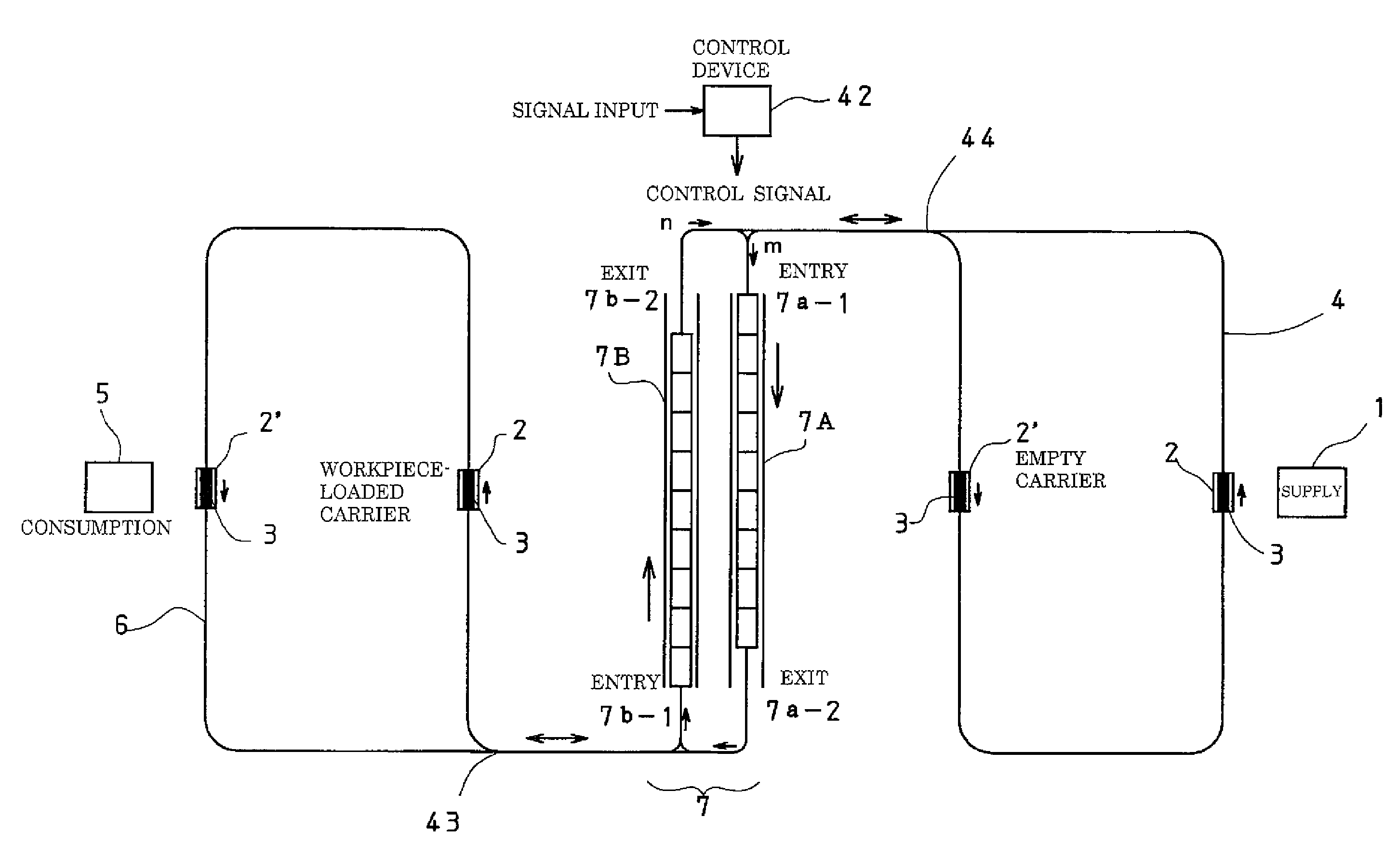
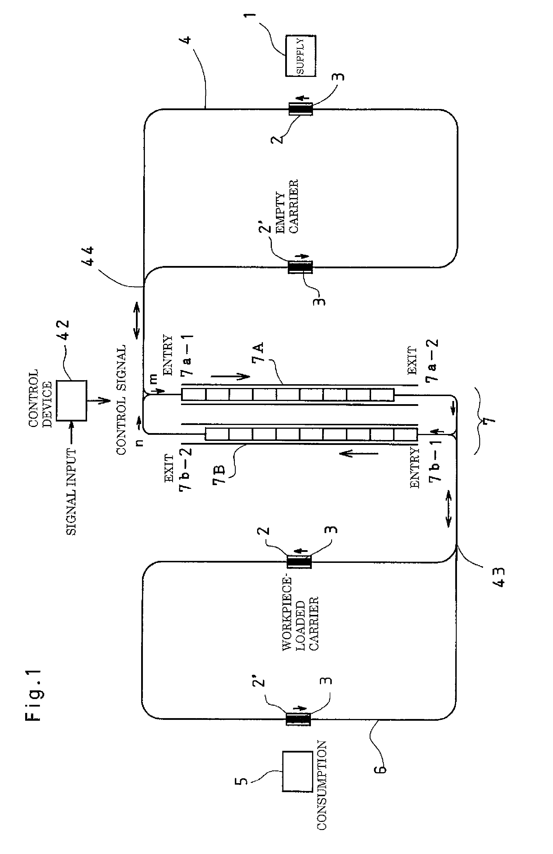
[0039]First, FIG. 1 is a conceptual diagram showing the plane configuration of a workpiece transportation system comprising automated transport vehicles 3 and workpiece carriers 2, as an embodiment of the present invention. A control device 42 denoted by reference sign 42 supervises and controls the overall system. Specifically, a variety of position detection signals etc. are fed to the control device 42, which processes them according to programs and feeds resulting control signals mostly to automated transport vehicles 3.

[0040]The workpiece transportation system shown in FIG. 1 comprises, as major elements, workpiece carriers 2 designed to be loaded with workpieces in a supply area 1 and transport them, automated transport vehicles 3 designed to cause the workpiece carrier 2 to travel with it and put and detach the workpiece carrier 2 in a predetermined position on a route, and a...

embodiment 2

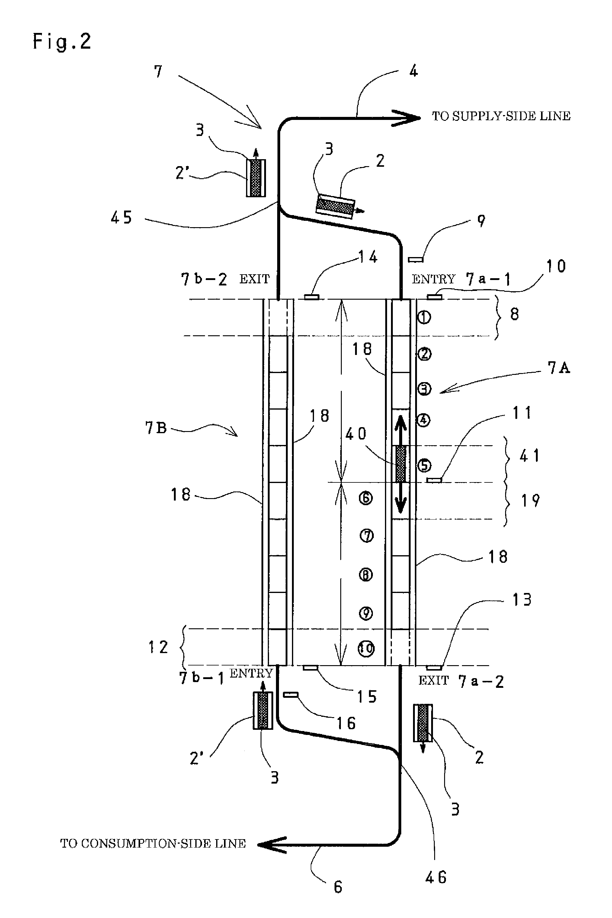
[0063]The above-described embodiment 1 is arranged such that workpiece-loaded carriers 2 that have entered the outward line section 7A of the buffer line 7, or empty carriers 2′ that have returned to the homeward line section 7B are fed as a series, or in other words, moved forward in a chain state, up to the fixed position 8 or 12 near the exit 7a-2 or 7b-2, so that the automated transport vehicle 3 entering each line section through the exit thereof takes out the carriers through the exit, one after another, in order of encountering.

[0064]However, in such series-feed method, the number of carriers that can be fed as a series is limited to the transport capacity of the automated transport vehicle 3. Particularly in the outward line section 7A intended to store workpiece-loaded workpiece carriers 2 which are great in weight, when the workpiece-loaded carriers 2 that have entered amount to 10 or so, it is not rare that the weight of the workpieces prevents the carriers 2 from being f...

embodiment 3

[0076]FIG. 6 is a conceptual diagram showing the plane configuration of another example of the workpiece transportation system comprising the automated transport vehicles 3 and the workpiece carriers 2, as embodiment 3 of the present invention.

[0077]The characterizing feature of embodiment 3 is that the outward line section 7A as well as the homeward line section 7B of the buffer line 7 consists of two (or more) lines.

[0078]It is to be noted that the supply-side line 4 as well as the consumption-side line 6 can be configured as desired, according to the practical requirements. In the example shown in FIG. 6, the consumption-side line 6 has branches corresponding to a plurality of consumption areas.


PUM


Abstract

A conveyance facility system for transporting an appropriate amount of work at a time at an appropriate time to the consumption side area by automatically controlling through a computer control system an automated guided vehicle for allowing a truck that has mounted the work in the supply side area to travel accompanying the vehicle from the supply side area to the consumption side area along the guidance course of the automated guided vehicle, and allowing the empty truck that has unloaded the work in the consumption side area to return to the supply side area. The work conveyance facility system comprises a plurality of work mounting trucks (2) for loading and conveying work, an automated guided vehicle (3) for allowing the work mounting truck (2) to travel accompanying the vehicle to a set position and releasing the truck thereat, and a guidance course of the automated guided vehicle (3). The guidance course is constituted of a supply side line (4) for loading the work onto the work mounting truck (2) in the supply area (1) and driving the truck, a consumption side line (6) for leading in the work mounting truck (2) and driving the empty work mounting truck (2′) that has unloaded the work in the consumption area (5), and a buffer line (7) for coupling the supply side line (4) with the consumption side line (6).

Description

BACKGROUND OF THE INVENTION[0001]1. Field of the Invention[0002]This invention belongs to the technical field of transportation systems in which, in order to transport workpieces (parts of mechanical devices, half-finished products, etc.) to a consumption-side (use-side) area at appropriate times in appropriate amounts, a computer control system automatically controls automated transport vehicles designed to cause a workpiece carrier that has been loaded with workpieces in a supply-side area to travel with it from the supply-side area to the consumption-side (use-side) area, along a guideway for the automated transport vehicle, and bring a workpiece carrier that has been emptied by unloading workpieces in the consumption-side (use-side) area (empty carrier) back to the supply-side area. More specifically, this invention relates to a workpiece transportation system which can be adapted to changes in workpiece transportation line, easily, without trouble, and which causes a homeward a...

Claims


Application Information

Patent Timeline
IPC IPC(8): B65G1/06
CPCB62D1/283B66C19/005B66F9/063G05B2219/50364G05B2219/31002G05B2219/32307G05B19/41895Y02P90/02Y02P90/60
Inventor NISHIMURA, KENICHIMATSUDA, HIROFUMIFUKUSHIMA, HIROHISA
Owner YAZAKI IND CHEM CO LTD
Learn More