Centrifugal compressor having vaneless diffuser and vaneless diffuser thereof

a centrifugal compressor and diffuser technology, which is applied in the direction of machines/engines, stators, liquid fuel engines, etc., can solve the problems of noise, vibration of shafts, and damage to impellers, and achieve the effect of preventing rotation, and preventing vibration of shafts

Active Publication Date: 2009-12-24
HITACHI IND PROD LTD
View PDF3 Cites 18 Cited by
  • Summary
  • Abstract
  • Description
  • Claims
  • Application Information

AI Technical Summary

Benefits of technology

[0008]The object of the present invention is, in a centrifugal compressor having an inlet flow channel, an impeller, a vaneless diffuser, and a return channel, to prevent rotatin

Problems solved by technology

In a high-pressure centrifugal compressor to handle high pressure gas, phenomena disturbing safe operation of the compressor such as noise, damage to an impeller, and vibration of shafting easily occur in comparison with a general centrifugal compressor.
It is considered that the s

Method used


Image

  • Centrifugal compressor having vaneless diffuser and vaneless diffuser thereof
  • Centrifugal compressor having vaneless diffuser and vaneless diffuser thereof
  • Centrifugal compressor having vaneless diffuser and vaneless diffuser thereof

Examples


first embodiment

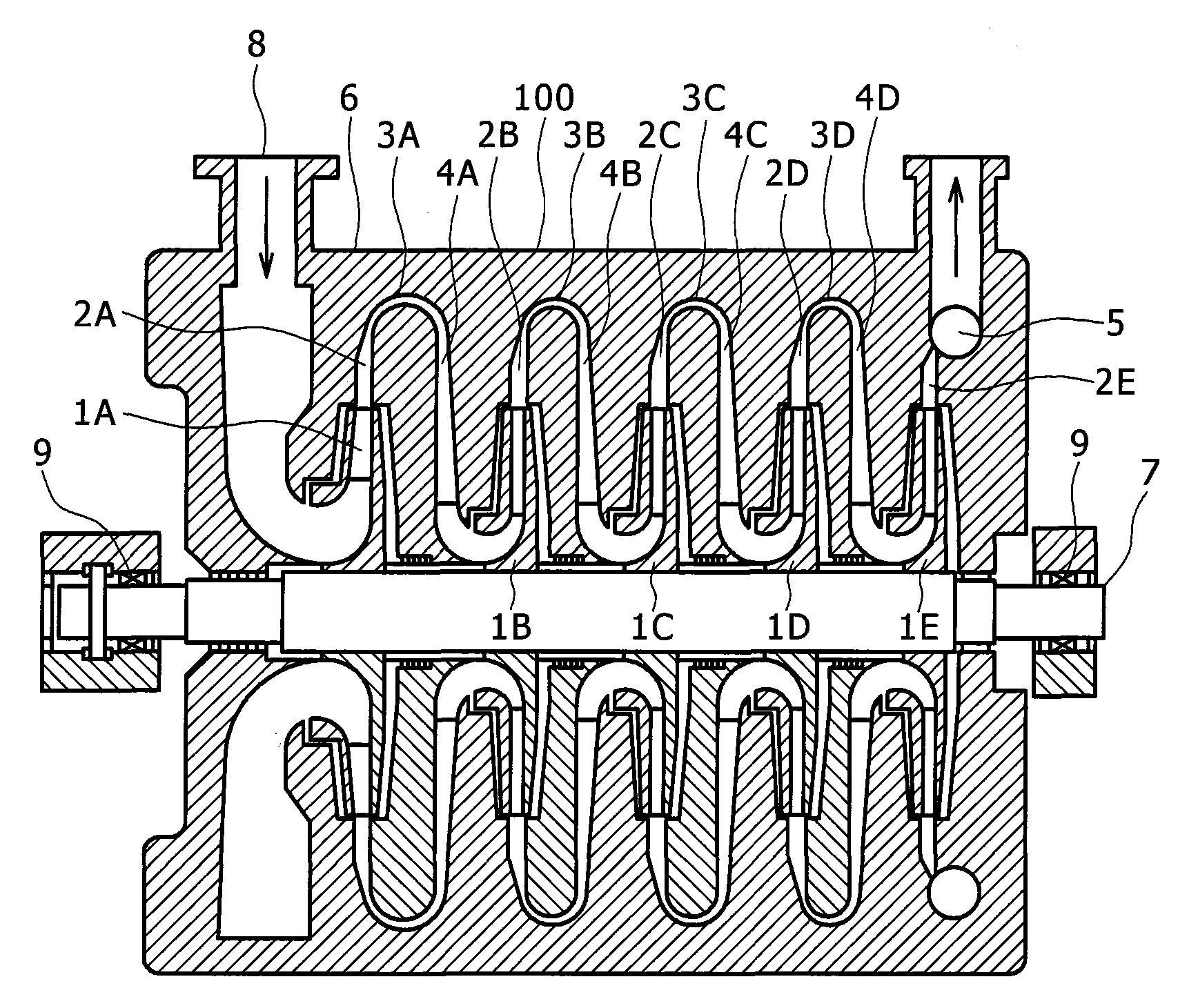
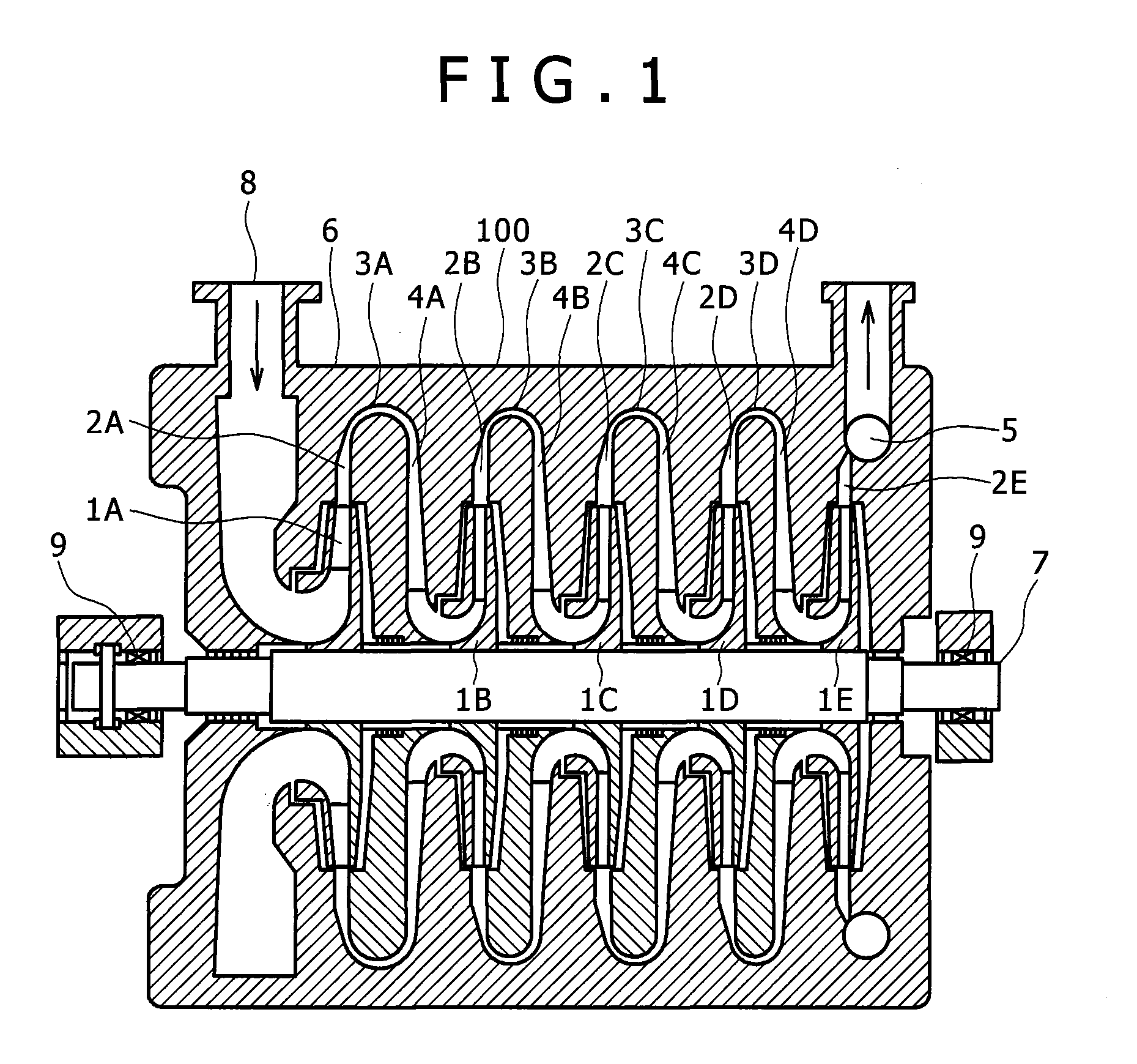
[0024]FIG. 1 shows a longitudinal cross-sectional shape of a single-shaft multi-stage centrifugal compressor according to a first embodiment of the present invention. A compressor stage having plural impellers 1A to 1E, diffusers 2A to 2E, return bends (return channels) 3A to 3D, and guide blades 4A to 4D, is arranged in an axial direction, thereby a single-shaft multi-stage centrifugal compressor 100 is formed. The plural impellers 1A to 1E stacked in the axial direction are attached to a rotating shaft 7, and both ends of the rotating shaft 7 are rotatably supported with bearings 9.

[0025]The diffusers 2A to 2E are provided on the outer side in the radial direction as a downstream side of the respective impellers 1A to 1E. The diffusers 2A to 2D in the respective stages except the final stage are connected to the return bends 3A to 3D to guide working fluid to the next stage, and the guide blades 4A to 4D to guide the working fluid inwardly in the radial direction are formed on the...

second embodiment

[0032]FIG. 5 shows a second embodiment and shows a longitudinal cross-sectional shape of the single-shaft multi-stage centrifugal compressor. The diffuser of the centrifugal compressor has first vaneless diffusers 21A to 21E with a constant flow channel height and second vaneless diffusers 22A to 22E, in which the flow channel height decreases in the flow direction, provided downstream from the first vaneless diffusers.

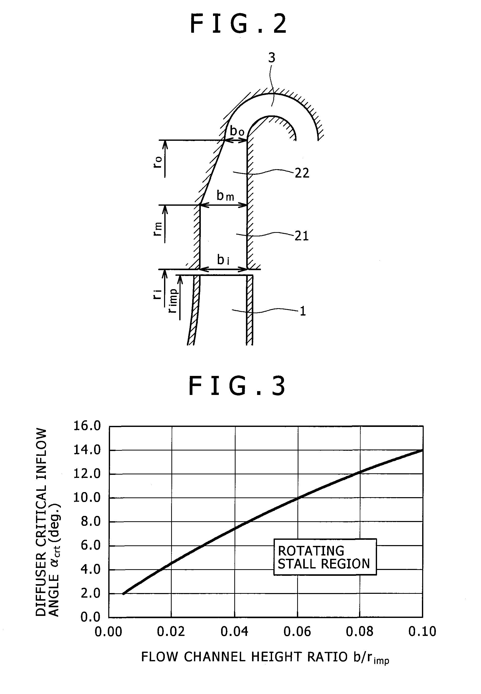
[0033]In this centrifugal compressor, the outlet height of the impeller becomes lower in the downstream stages since the volume flow rate becomes smaller in the lower stage. Accordingly, the inlet flow channel heights bmA to bmE of the second vaneless diffusers 22A to 22E, in which the flow channel height gradually decreases in the flow direction from the inlet to the outlet in the respective stages, become lower in the downstream stages. The radial positions rmA to rmE of the inlets of the second vaneless diffusers are smaller in the downstream stages. That is, an in...

third embodiment

[0036]As a third embodiment, a diffuser drawing ratio is logically calculated from the result of measurement of the flow angle in the parallel wall vaneless diffuser, and based on the experimental measurement, the outlet flow channel height bo of the second vaneless diffuser in FIG. 2 is set to 0.4 to 0.6 times of the inlet flow channel height bm of the second vaneless diffuser. When the value of bo / bm is too large, the effect of decrease in the flow channel height is reduced, while when the value of bo / bm is too small, the flow velocity is too high and the frictional loss is increased.


PUM


Abstract

In a high pressure centrifugal compressor, the occurrence of rotating stall noticeable in a comparatively-low specific speed wheel stage is prevented, thereby high efficient fluid performance is obtained and reliability is improved. The centrifugal compressor has a first vaneless diffuser with a constant flow channel height on the downstream side of an impeller, and a second vaneless diffuser in which the flow channel height decreases in a flow direction from an inlet to an outlet on the downstream side of the first vaneless diffuser. These diffusers are combined with an impeller using thick blades.

Description

[0001]The present application claims priority from Japanese application JP2008-162882 filed on Jun. 23, 2008, the content of which is hereby incorporated by reference into this application.BACKGROUND OF THE INVENTION[0002]The present invention relates to a centrifugal compressor and a diffuser used therein, and more particularly, to a centrifugal compressor and a centrifugal blower to handle comparatively low flow rate gas, and a diffuser used therein.[0003]In a high-pressure centrifugal compressor to handle high pressure gas, phenomena disturbing safe operation of the compressor such as noise, damage to an impeller, and vibration of shafting easily occur in comparison with a general centrifugal compressor. One of the phenomena is rotating stall.[0004]The rotating stall occurs mainly in a comparatively-low specific speed impeller stage. It is considered as the mechanism of the rotating stall that the rotating stall occurs due to a reverse flow which occurs in a flow in the diffuser....

Claims


Application Information

Patent Timeline
IPC IPC(8): F04D29/44
CPCF04D29/441F04D17/122
Inventor TANAKA, MASANORINISHIDA, HIDEOKOBAYASHI, HIROMIKUWANO, TETSUYAITOU, TOSHIO
Owner HITACHI IND PROD LTD
Why Eureka
Try Eureka