Dilator Loading Catheter

a technology of dilator and catheter, which is applied in the direction of trachea tubes, stents, respirators, etc., can solve the problems of increasing the likelihood that an item may be accidentally rendered unsterile and cannot be used,

Inactive Publication Date: 2009-12-31
KIMBERLY-CLARK WORLDWIDE INC
View PDF39 Cites 35 Cited by
  • Summary
  • Abstract
  • Description
  • Claims
  • Application Information

AI Technical Summary

Problems solved by technology

In addition, the large number of parts used in current tracheostomy kits increases t...

Method used


Image

  • Dilator Loading Catheter
  • Dilator Loading Catheter
  • Dilator Loading Catheter

Examples


Embodiment Construction

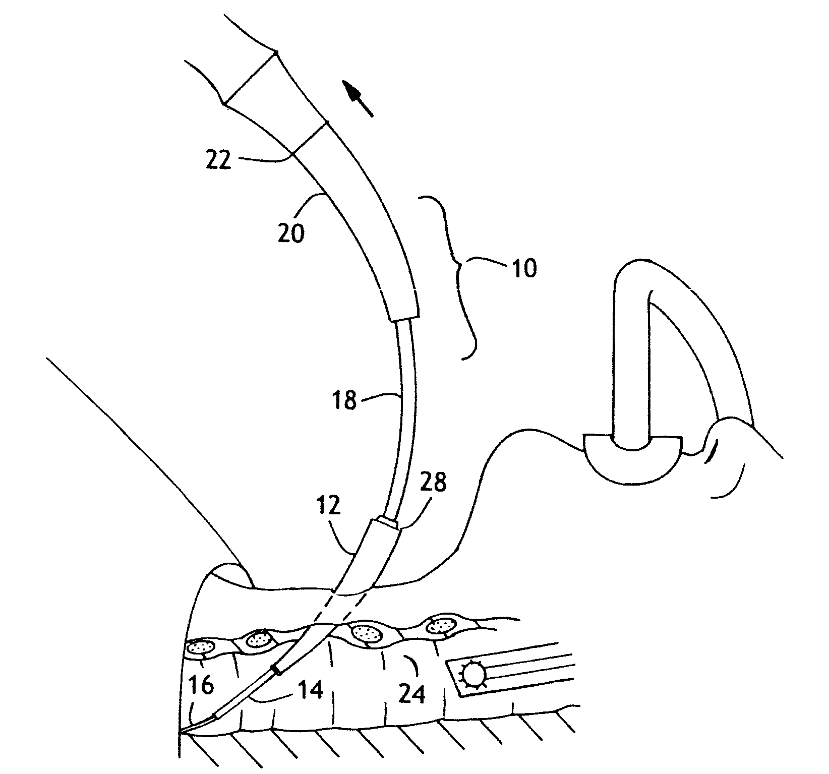
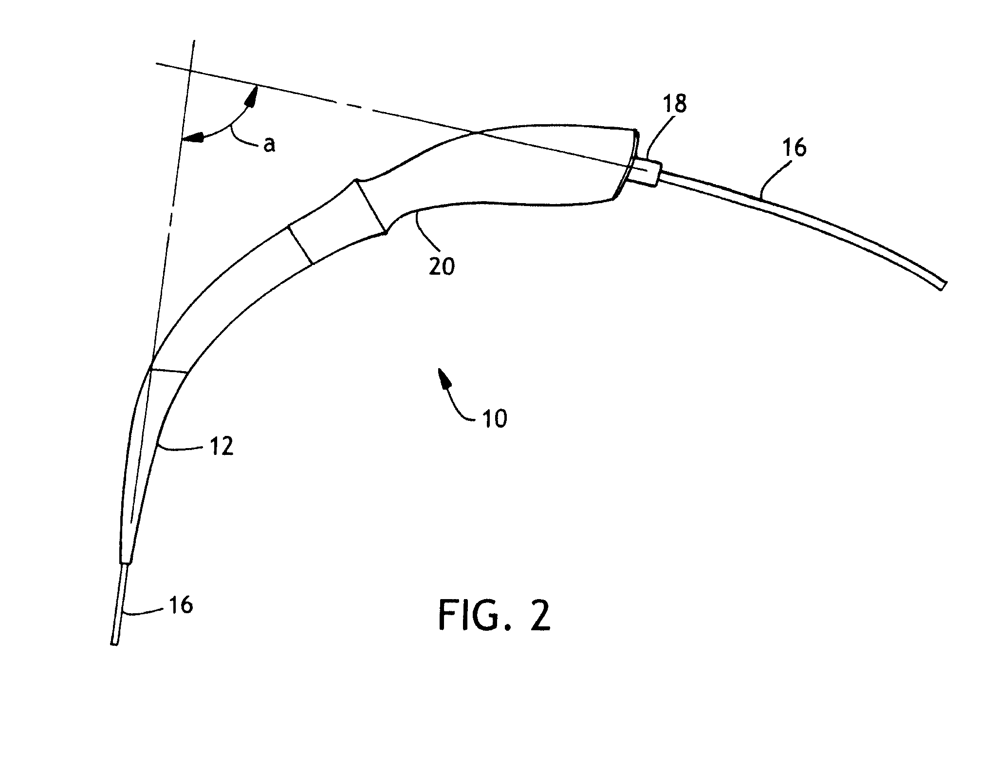
[0024]Tracheostomy is a lifesaving procedure to allow a patient to be ventilated directly through the trachea. Tracheostomy is also believed by many to prevent or retard the onset of ventilator acquired pneumonia (VAP). This lifesaving procedure, unfortunately, is relatively time consuming and current technology requires a large number of steps and pieces of equipment that must remain sterile and functioning properly in order to arrive at a successful conclusion. The tracheostomy procedure may be greatly improved using the loading catheter described in the Summary above in conjunction with the novel easy grip tapered dilator.

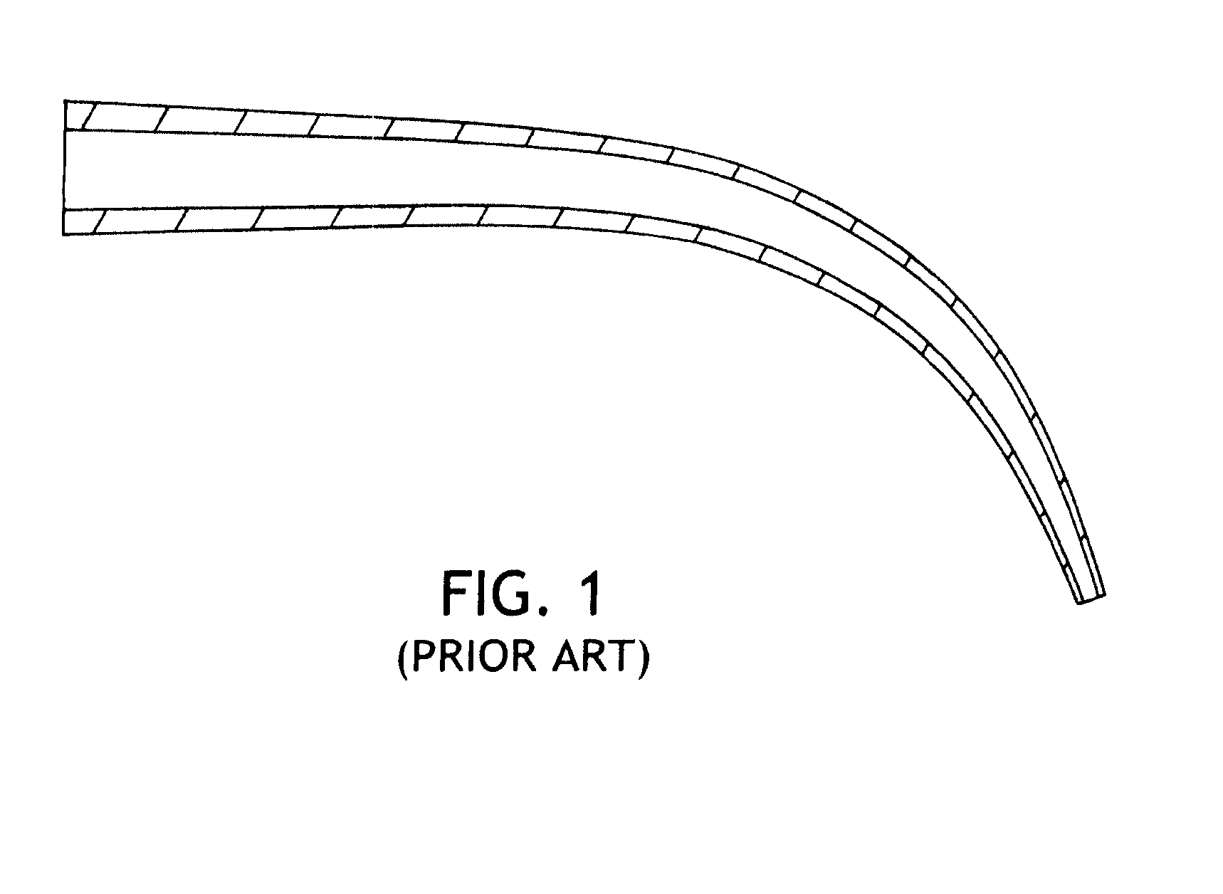
[0025]Dilators are instruments or substances for enlarging a canal, cavity, blood vessel or opening, according to the American Heritage Stedman's Medical dictionary 2001. FIG. 1 is a drawing of the prior art dilator from Cook Medical Inc. known as the Blue Rhino® dilator (see also U.S. Pat. No. 6,637,435). The '435 patent describes a one piece dilator having a g...


PUM


Abstract

There is provided a device for removing a tracheotomy dilator. The dilator has a body and a tip which are detachably attached. After dilating the trachea, the body is removed, leaving only the tip in the tracheal opening. The dilator tip loading catheter has a distal end adapted to engage the proximal end of the dilator tip, a proximal handle, and a mid-section therebetween. The device also has a cannula therethrough. The proximal handle can detachably attach to the proximal end of the tracheostomy tube. The distal end and mid-section of the device are sized to fit into the cannula of a tracheostomy tube. The distal end and mid-section of the device may be inserted into a tracheostomy tube, the distal end then mating with the proximal end of the dilator tip. The entire assembly may be moved into the trachea. Once the trach tube is in position, the loading catheter and tip may be withdrawn through the trach tube.

Description

[0001]Ventilators or respirators are used for mechanical ventilation of the lungs of a patient in a medical setting. The ventilator unit is connected to a hose set; the ventilation tubing or tubing circuit, delivering the ventilation gas to the patient. At the patient end, the ventilation tubing is typically connected to a tracheal ventilation catheter or tube, granting direct and secure access to the lower airways of a patient. Tracheal catheters are equipped with an inflated sealing balloon element, or “cuff”, creating a seal between the tracheal wall and tracheal ventilation tube shaft, permitting positive pressure ventilation of the lungs.[0002]One type of tracheal catheter, an endotracheal tube (ET tube), inserted through the mouth, is generally used for a number of days before a decision is made to switch a patient to a tracheostomy tube, inserted directly into the trachea through a stoma in the tracheal wall. Endotracheal tubes have been linked in some studies to an increased...

Claims


Application Information

Patent Timeline
IPC IPC(8): A61M16/04A61F2/958
CPCA61M16/0434A61M16/0465A61M16/0497A61M16/0488A61M16/0472
Inventor CUEVAS, BRIAN J.SLEVA, MICHAELCESA, JOE
Owner KIMBERLY-CLARK WORLDWIDE INC
Why Eureka
Try Eureka