Drill bit having functional articulation to drill boreholes in earth formations in all directions

a drilling bit and functional technology, applied in the direction of drilling machines, drilling methods, directional drilling, etc., can solve the problems of poor lateral response, limited directional drilling capabilities, and inability to reliably allow controlled drilling, so as to prevent lateral cutting, restrict the diameter of the borehole, and limit the length of the cutting surface

Inactive Publication Date: 2009-12-31
TERCEL IP
View PDF21 Cites 11 Cited by
  • Summary
  • Abstract
  • Description
  • Claims
  • Application Information

AI Technical Summary

Benefits of technology

[0014]In an embodiment of the invention, the cutting surfaces of the second plurality of cutters can define the outer circumference of the drill bit. Conventional drill bits have flattened and / or rounded cutter elements, ground to the desired diameter of the borehole to prevent lateral cutting. The present drill bit, however, can present a cutting surface along its outer circumference to enable lateral boring and other changes in drilling direction that would not be possible with a conventional bit.
[0015]In a further embodiment of the invention, an outermost portion of a cutter on the second bit face and an innermost portion of a cutter on the first bit face can be angularly displaced from one another by greater than ninety degrees. While conventional drill bits include gage retention mechanisms and other devices to restrict the diameter of the borehole and limit the length of the cutting surface, the present drill bit can include cutters disposed along the shaft of the bit body, providing a cutting radius in excess of ninety degrees. Independent of the angular displacement between cutters, the first and second pluralities of cutters can provide the drill bit with a continuous cutting surface.

Problems solved by technology

Though some drill bits omit use of gage pads and other gage retention mechanisms, or use shortened gage pads combined with dulled or flat cutters to resist wear, these drill bits do not reliably allow for a controlled formation of oversized boreholes and are often limited in their directional drilling capabilities, providing a poor lateral response.

Method used


Image

  • Drill bit having functional articulation to drill boreholes in earth formations in all directions
  • Drill bit having functional articulation to drill boreholes in earth formations in all directions
  • Drill bit having functional articulation to drill boreholes in earth formations in all directions

Examples


Embodiment Construction

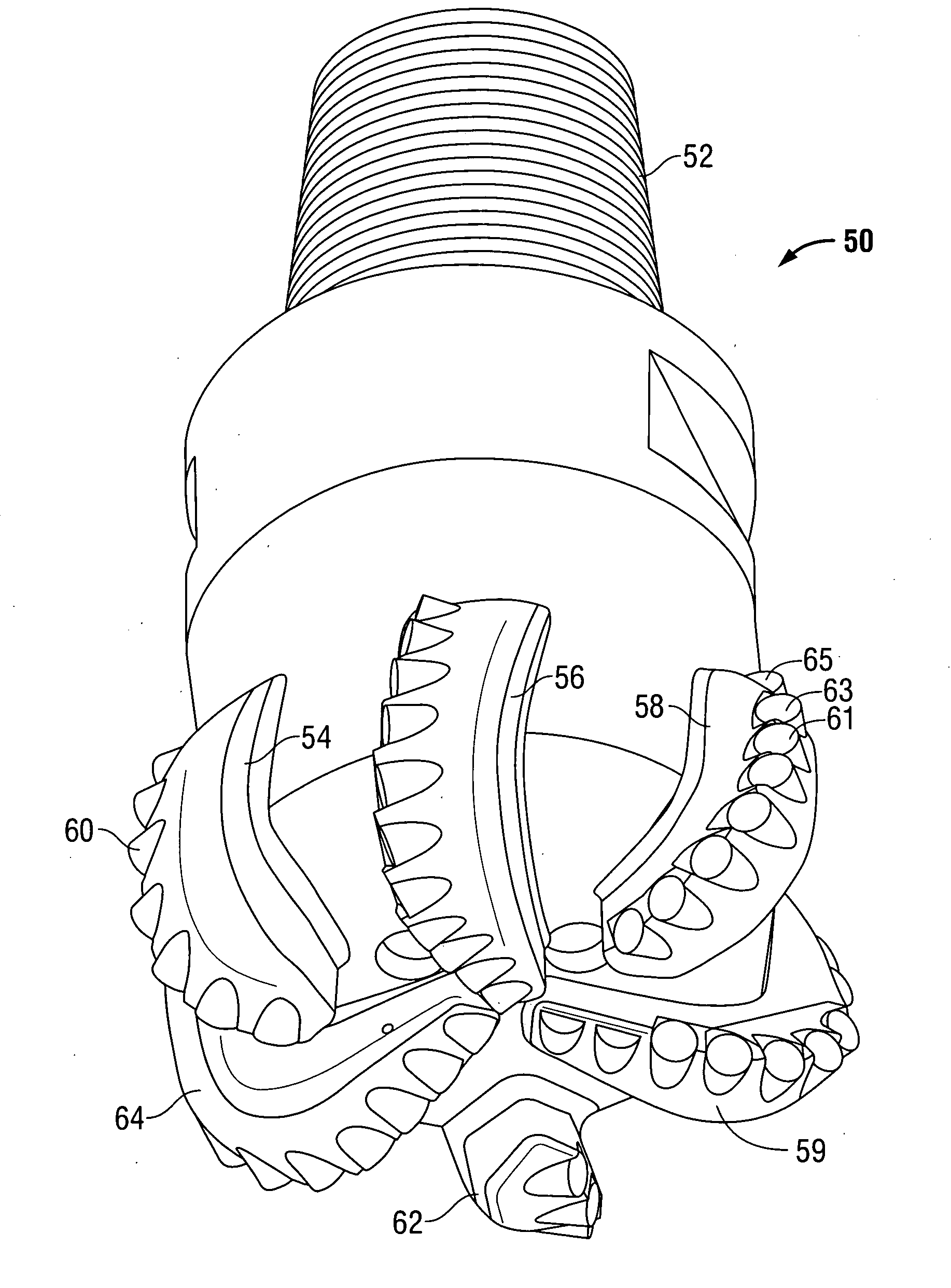
[0034]Drill bits manufactured and used according to the preferred embodiments of the present invention, being designed to enable functional articulation between the drill bit and the tubular drillstring, are designed to drill in all directions, including forward (downward) in a vertical direction, horizontally, laterally (360°), upward (in a vertical direction,) and at all angels therebetween. This major advance in drill bit technology is accomplished, in part, by using cutters having cutting surfaces set in the flank of the bit, in which the backrake angles of such flank-set cutter ing surfaces each provide a drilling edge via a relief angle produced by the backrake angle.

[0035]FIG. 3 depicts a pictorial view of an embodiment of a drill bit 50 according to the present invention. The drill bit 50 is shown having a threaded pin end 52 for engaging a drill string (not illustrated). The drill bit 50 is further shown having a plurality of blades 54, 56, 58, 59, 62, and 64 disposed there...


PUM


Abstract

A drill bit is described herein, having a first bit face with a first plurality of cutters oriented to bore in a first direction, and a second bit face with a second plurality of cutters oriented to bore in one or more second directions. The pluralities of cutters enable functional articulation of the drill bit, such that the drill bit can change direction within a borehole without requiring removal of the drill bit. The drill bit can thereby drill in a downhole direction and lateral directions, can back ream through the borehole, and can provide the borehole with one or more oversized regions, as desired.

Description

CROSS-REFERENCE TO RELATED APPLICATIONS[0001]This application is a continuation-in-part application, which claims priority to the United States Patent Application having the application Ser. No. 12 / 215,435, filed Jun. 27, 2008, entitled DRILL BIT HAVING HAVING THE ABILITY TO DRILL VERTICALLY AND LATERALLY.FIELD OF THE INVENTION[0002]The present invention relates, generally, to drill bits used for drilling oil and gas wells, and more specifically, to a drill bit capable of drilling in any of a plurality of directions, including backreaming, and drilling oversize boreholes, through a form of functional articulation.BACKGROUND OF THE INVENTION[0003]Drill bits for drilling a borehole within an earth formation are generally well known in the art. Many conventional drill bits are designed to use cutters that include blades having polycrystalline diamond compact (PDC) cutter elements affixed thereon, mounted on a rotary bit, with the PDC cutter elements arranged such that each engages an e...

Claims


Application Information

Patent Timeline
Patent Type & Authority Applications(United States)
IPC IPC(8): E21B7/04E21B10/00
CPCE21B10/43
Inventor SHAMBURGER, JAMESWILDE, DAVID
Owner TERCEL IP
Why Eureka
Try Eureka