Methods of electromagnetic forming aluminum alloy wheel for automotive use

a technology of electromagnetic forming and aluminum alloy wheel, which is applied in the direction of engine components, mechanical equipment, transportation and packaging, etc., can solve the problems of affecting the geometric accuracy the problem of the wheel rim being joined with the disc used, and the general weight of aluminum alloy wheel manufactured by casting. , to achieve the effect of improving geometric accuracy, high forming accuracy and large diameter

Inactive Publication Date: 2008-10-28
KOBE STEEL LTD
View PDF19 Cites 5 Cited by
  • Summary
  • Abstract
  • Description
  • Claims
  • Application Information

AI Technical Summary

Benefits of technology

[0026]Still further, with the method of manufacturing the automotive wheel according to the invention, the following effects and advantages are obtained as to only the process of forming the wheel rim out of the columnar workpiece. Such advantageous effects also contribute to enhancement in efficiency of the method of manufacturing the automotive wheel according to the invention.
[0027]When the columnar workpiece undergoes flaring at the time of the electromagnetic forming, the columnar workpiece is first pressed against a central part, small in diameter, (corresponding to the drop part of the wheel rim) of the forming face of the metal mold for the electromagnetic forming, and is subsequently first pressed against respective portions, larger in diameter, (corresponding to both the side parts of the wheel rim) of the forming face, on both sides of the central part, so that air existing in gaps between the metal mold and the columnar workpiece can easily escape in the axial direction of the mold in the course of the electromagnetic forming, thereby minimizing a risk that the air is trapped between material and the forming face to be thereby pressurized, causing a problem that the air at high pressure interferes with the material being pressed against the forming face.
[0028]Accordingly, with the method of manufacturing the wheel according to the invention, trapped air is allowed to vent, as necessary, without orifices or slits, particularly for serving as vents, provided in the metal mold, or with relatively small orifices or slits provided, so that high forming accuracy can be obtained. In particular, if the inside diameter of the forming face of the metal mold, gradually increases from a spot (the central part) of the forming face, corresponding to the drop part of the wheel rim, toward the respective end sides thereof, in the axial direction, without any spot where the inside diameter decreases part of the way, the air can easily escape in the axial direction.
[0029]With the method of manufacturing the wheel according to the invention, a columnar workpiece of a diameter equivalent to, or slightly smaller than the diameter of a spot of the wheel rim having the smallest diameter after forming is used as the columnar workpiece for use in the electromagnetic forming. Accordingly, it follows that in forming a wheel rim of an identical diameter, use is made of a columnar workpiece fairly smaller in diameter than that in the case of necking down the columnar workpiece by the electromagnetic forming. This means that, in the case of using an aluminum alloy extrusion as the columnar workpiece, the upper limit of the diameter of the wheel rim that can be manufactured is expanded (that is, an extrusion can be used for manufacturing even a wheel rim still larger in diameter). Further, an aluminum alloy extrusion, in the shape of a pipe, is caused to undergo flaring by applying the electromagnetic forming thereto, and is then used as a cylindrical workpiece, thereby expanding further the upper limit of the diameter of the wheel rim that can be manufactured. Also, in the case of using an extrusion with a columnar sidewall in the cross-sectional shape of waves continuous along the circumferential direction thereof as the columnar workpiece, it is possible to expand the upper limit of the diameter of the wheel rim that can be manufactured. That is, as the columnar sidewall of the extrusion is in the cross-sectional shape of the waves, the columnar workpiece has rigidity higher than that for a simple cylindrical workpiece, so that geometrical accuracy is improved, thereby enabling a wheel rim larger in diameter to be manufactured.
[0030]As described hereinbefore, with the present invention, the wheel rim with both the side parts thereof, smaller in wall thickness, than the drop part thereof is inevitably obtained. The wheel rim with both the side parts smaller in wall thickness, than the drop part is preferable from the viewpoint of reduction in weight of the wheel rim in whole. Among advantages of the method of manufacturing the wheel according to the invention, there is included capability of manufacturing the wheel rim as described out of the columnar workpiece uniform in wall thickness.
[0031]Furthermore, the invention is advantageous in that a face of the columnar workpiece undergoing flaring, on the inner peripheral side thereof, is not butted against the forming face of the metal mold for the electromagnetic forming, so that the inner peripheral side of the wheel rim (a face thereof, visible from outside when the wheel rim is attached to an automobile) is not marred due to the forming.

Problems solved by technology

An aluminum alloy wheel manufactured by casting is generally heavy in weight (although lighter as compared with a steel wheel), and is expensive, so that it is used mainly for an upscale automobile.
An aluminum alloy wheel manufactured by forging is excellent in mechanical property, but very expensive, so that it is used for special purposes.
However, in the case of the method of manufacturing the wheel, comprising the steps of forming the columnar workpiece into the wheel rim, and subsequently, combining the wheel rim with the disc separately formed, joining of the wheel rim with the disc used to pose a problem.
Accordingly, the method has been difficult to be made commercially viable.
As execution of the joining as described by a simple welding will cause a problem of the formation of thinned material regions, due to weld strain and thermal effect, welding has been difficult to apply.
In order to preclude the problem, orifices or slits, serving as vents, may be provided in the metal mold as appropriate, however, to enable the air to vent sufficiently, there is the need for providing a multitude of the orifices or the slits, largish in size, along the forming face, resulting in an increase in the cost of the metal mold as well as deterioration in design versatility due to the columnar workpiece being pressed against the orifices or the slits to thereby undergo deformation.(2) In the case of applying the electromagnetic forming to the columnar workpiece so as to neck down the columnar workpiece, the inner peripheral face side of the wheel rim (a face thereof, visible from outside when the wheel rim is attached to an automobile) is butted against the forming face of the metal mold for the electromagnetic forming, and is susceptible to being marred.
However, the following problem is further encountered in the case of applying the electromagnetic forming so as to neck down a columnar extrusion.
That is, because the columnar workpiece needs to have a diameter equal to, or slightly larger than the diameter of a part of the wheel rim after the completion of the electromagnetic forming, largest in diameter, there can be a case where it is difficult to provide a suitable columnar workpiece (the larger the diameter of an extrusion, the more difficult it is to execute extrusion molding) depending on the diameter of the wheel rim, in demand.

Method used


Image

  • Methods of electromagnetic forming aluminum alloy wheel for automotive use
  • Methods of electromagnetic forming aluminum alloy wheel for automotive use
  • Methods of electromagnetic forming aluminum alloy wheel for automotive use

Examples


working example

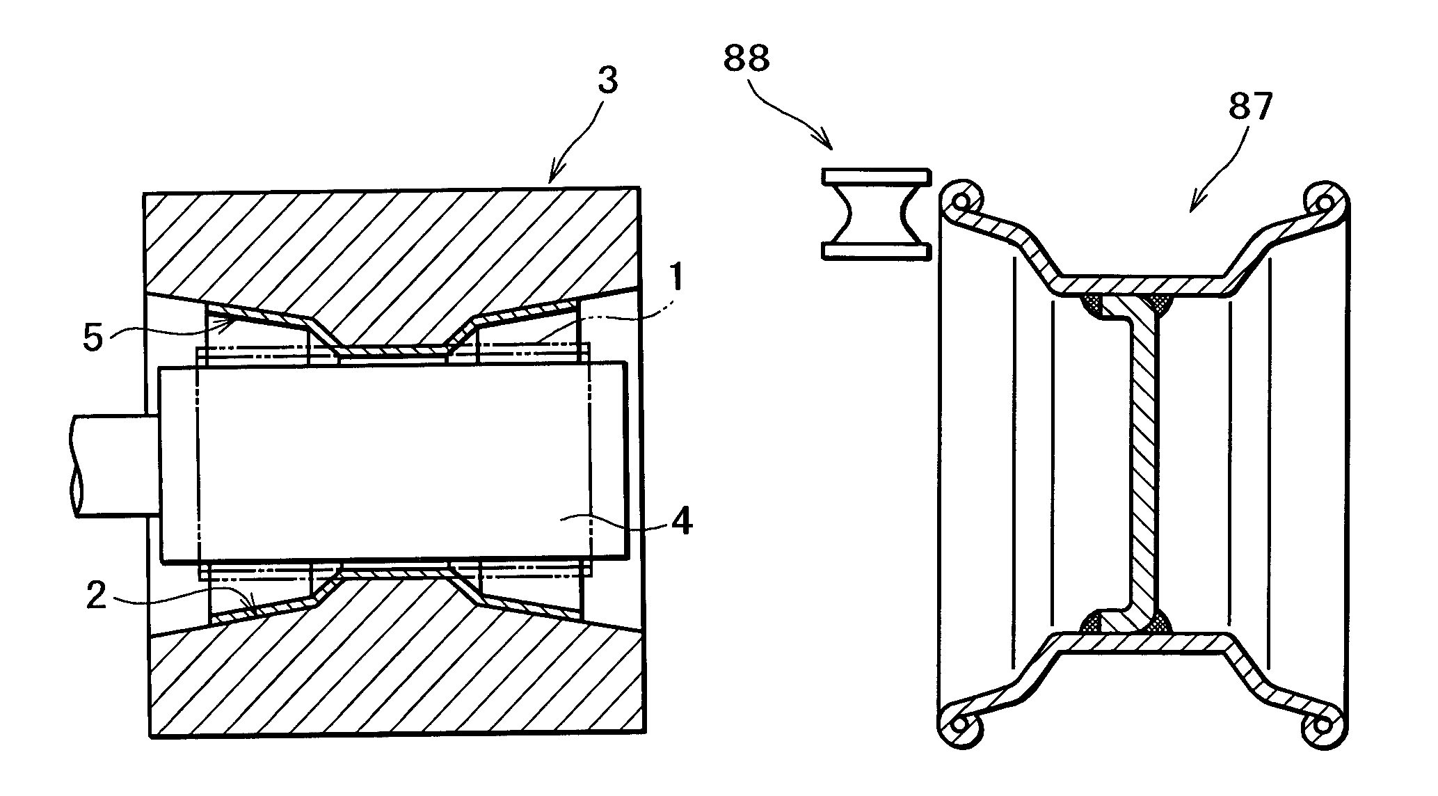
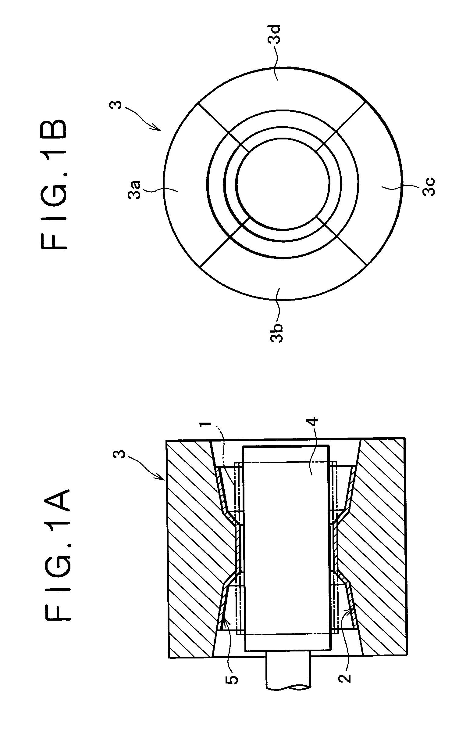
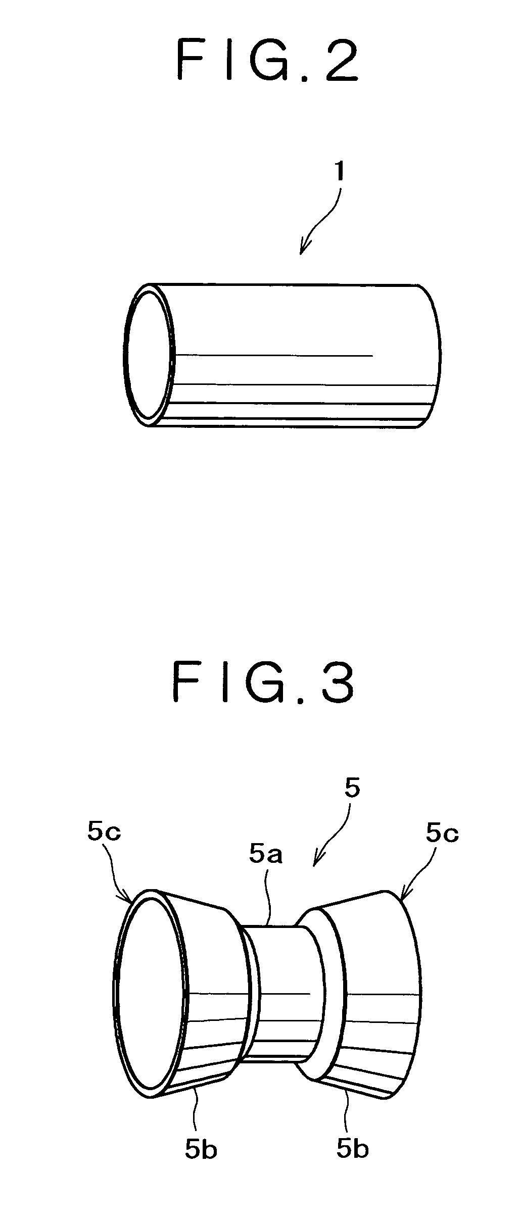
[0085]In accordance with the embodiment of the invention, use was made of a columnar workpiece 200 mm in inside diameter, 3.0 mm in wall thickness, and 300 mm in length, prepared from an aluminum alloy extrusion (6063 among the O-alloys), circular in shape, the columnar workpiece was set inside a metal mold for electromagnetic forming, as shown in FIG. 1, and a coil for electromagnetic forming, 198 mm in outside diameter, and 300 mm in length, was inserted into the columnar workpiece, whereupon the columnar workpiece was subjected to the electromagnetic forming at discharged electric energy of 30 kJ to undergo flaring, thereby obtaining a wheel rim. Respective sectional shapes of the columnar workpiece, and the wheel rim thus obtained are shown in FIGS. 13(a) and 13(b), respectively.

[0086]As shown in FIG. 13(b), the outside diameter of a drop part 5a of the wheel rim after the electromagnetic forming was found at 206 mm, the outside diameter of each of rim outer rim edges 5c at 305 ...


PUM

PropertyMeasurementUnit
diameteraaaaaaaaaa
diameteraaaaaaaaaa
diameteraaaaaaaaaa

Abstract

A metal mold for electromagnetic forming, with the inner peripheral face thereof, serving as a forming face, is disposed on the outer peripheral side of a columnar workpiece, and a coil for electromagnetic forming is disposed on the inner peripheral side of the columnar workpiece. In a state of a configuration as described, electric energy is thrown into the coil for the electromagnetic forming, and the columnar workpiece is caused to undergo flaring to be thereby pressed against the forming face of the metal mold for the electromagnetic forming, so as to be turned into a shape corresponding to the forming face by means of the electromagnetic forming, thus obtaining a wheel rim. A disc is welded to the wheel rim obtained, and curling is applied to outer edges of the wheel rim. With the adoption of a method of manufacturing an automotive wheel, a manufacturing process as a whole is enhanced in efficiency.

Description

BACKGROUND OF THE INVENTION[0001]1. Field of the Invention[0002]The present invention relates to a method of manufacturing an automotive wheel and wheel rim, made out of an aluminum alloy sheet or extrusion.[0003]2. Description of the Related Art[0004]As a method of manufacturing an aluminum alloy wheel for use in a passenger car, truck, buggy, and so forth, there have been known three processes of casting, forging, and press working. An aluminum alloy wheel manufactured by casting is generally heavy in weight (although lighter as compared with a steel wheel), and is expensive, so that it is used mainly for an upscale automobile. An aluminum alloy wheel manufactured by forging is excellent in mechanical property, but very expensive, so that it is used for special purposes. Meanwhile, an aluminum alloy wheel manufactured by press working is advantageous in that it is light in weight, and can be manufactured at a low cost.[0005]In Utility Model Laid-open No. 1988-56935, it is describe...

Claims


Application Information

Patent Timeline
Patent Type & Authority Patents(United States)
IPC IPC(8): B23P17/00B21D53/30
CPCB21D53/30Y10T29/49529Y10S72/707Y10T29/49803Y10T29/49499Y10T29/49524
Inventor IMAMURA, YOSHIHAYAYAMASHITA, HIROYUKI
Owner KOBE STEEL LTD
Why Eureka
Try Eureka