Optimizing feed mixer performance in a paraffinic froth treatment process

a paraffinic froth treatment and feed mixer technology, applied in the field of hydrocarbon production, can solve the problems of toughest energy challenges

Active Publication Date: 2009-12-31
EXXONMOBIL UPSTREAM RES CO
View PDF15 Cites 18 Cited by
  • Summary
  • Abstract
  • Description
  • Claims
  • Application Information

AI Technical Summary

Problems solved by technology

The economic recovery and utilization of heavy hydrocarbons, including bitumen, is one of the world's toughest energy challenges.
They were used because it was thought that high shear in settling tanks was detrimental to settling and that low shear only impacted quantity of material precipitated, not the precipitation rate.

Method used


Image

  • Optimizing feed mixer performance in a paraffinic froth treatment process
  • Optimizing feed mixer performance in a paraffinic froth treatment process
  • Optimizing feed mixer performance in a paraffinic froth treatment process

Examples


examples

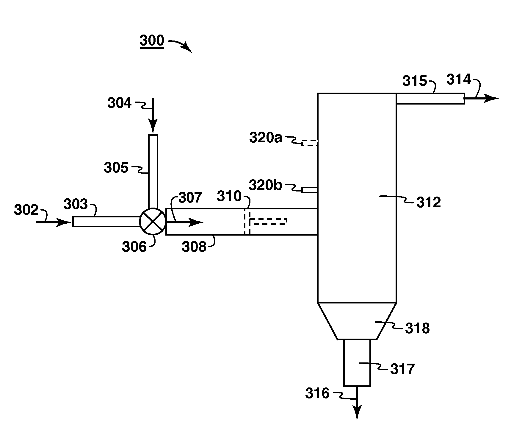
[0038]FIG. 4 is a graph showing exemplary results of testing done in a pilot plant utilizing the system 300. The graph 400 compares solids concentration in parts per million weight (ppmw) 402 versus average shear rate in inverse seconds (s-1) 404 at a flux rate of about 550 millimeters per minute (mm / min). The diamonds show the concentration of solids (clay type material) in the product 307 at varying shear rates in the feed pipe 308. These measurements were taken from a location well above the feed pipe inlet at a location like port 320a. Shear was changed by varying the feed pipe 308 diameter. From the graph 400, it appears that a shear rate of about 125 s−1 can be considered optimal. However, a 40-3,200 s−1 was tested and found still to be under the design target 406 of about 125 ppmw. The circular dots indicate measurements of the concentration of the solids a few inches above the feed location, such as via port 320b. In other words, these measurements were taken just above the ...


PUM

PropertyMeasurementUnit
temperatureaaaaaaaaaa
operating pressuresaaaaaaaaaa

Abstract

The invention relates to improved bitumen recovery processes and systems. One process provides for operation of a bitumen froth treatment plant at optimum shear rates in the feed pipe carrying the bitumen froth to the froth settling unit. Another process provides for optimizing the design of a bitumen froth treatment plant by optimizing the diameter of the feed pipe to impart an optimum shear rate to the bitumen froth mixture and further optimizing the volume of the feed pipe to impart an optimum residence time for the bitumen froth stream in the feed pipe. An optimal plant design is also disclosed, the plant including optimal diameter and volume of the feed pipe.

Description

CROSS REFERENCE TO RELATED APPLICATION[0001]This application claims the benefit of U.S. Provisional Application No. 61 / 133,309, filed Jun. 27, 2008.FIELD OF THE INVENTION[0002]The present invention relates generally to producing hydrocarbons. More specifically, the invention relates to methods and systems for optimizing the performance of feed mixing devices in a solvent based froth treatment process.BACKGROUND OF THE INVENTION[0003]The economic recovery and utilization of heavy hydrocarbons, including bitumen, is one of the world's toughest energy challenges. The demand for heavy crudes such as those extracted from oil sands has increased significantly in order to replace the dwindling reserves of conventional crude. These heavy hydrocarbons, however, are typically located in geographical regions far removed from existing refineries. Consequently, the heavy hydrocarbons are often transported via pipelines to the refineries. In order to transport the heavy crudes in pipelines they m...

Claims


Application Information

Patent Timeline
Patent Type & Authority Applications(United States)
IPC IPC(8): C10G1/00C10C3/08G05D7/00
CPCC10G1/047C10G1/045
Inventor SHARMA, ARUN K.RATERMAN, MICHAEL F.
Owner EXXONMOBIL UPSTREAM RES CO
Why Eureka
Try Eureka