Method to improve the characteristics of a root pass pipe weld

a technology of root pass pipe and weld characteristics, which is applied in the field of electric arc welding, can solve the problems of pipeline welding, time-consuming and expensive, and difficulty in welding open root pipe, and achieves the effects of improving the characteristics and improving the quality of root pass pipe welds

Active Publication Date: 2009-12-31
LINCOLN GLOBAL INC +1
View PDF43 Cites 16 Cited by
  • Summary
  • Abstract
  • Description
  • Claims
  • Application Information

AI Technical Summary

Benefits of technology

[0010]Embodiments of the present invention comprise a method and a system for forming a root pass weld for a root pipe joint. A substantially periodic electric welding waveform is generated and a series of electric arc pulses are generated between an advancing welding electrode and a root pipe joint in response to the electric welding waveform. The electric welding waveform includes a base cycle having a background current phase...

Problems solved by technology

It is difficult, even for skilled welders, to weld open root pipe.
Inflexible positioning makes pipeline welding more difficult, time consuming, and expensive.
Gas tungsten arc welding (GTAW) has been an available process capable of achieving the quality requirements, however, GTAW root welds are expens...

Method used


Image

  • Method to improve the characteristics of a root pass pipe weld
  • Method to improve the characteristics of a root pass pipe weld
  • Method to improve the characteristics of a root pass pipe weld

Examples


Embodiment Construction

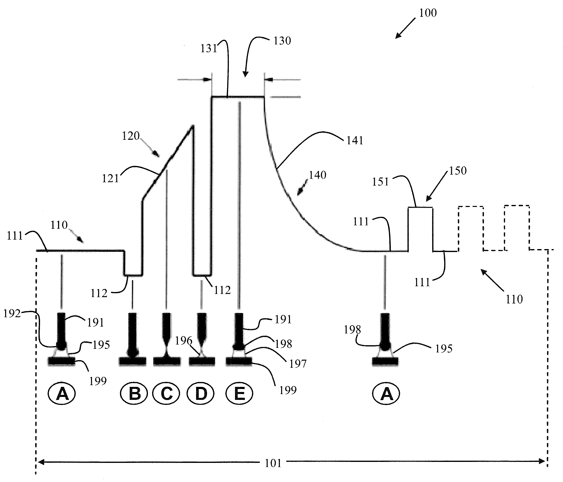
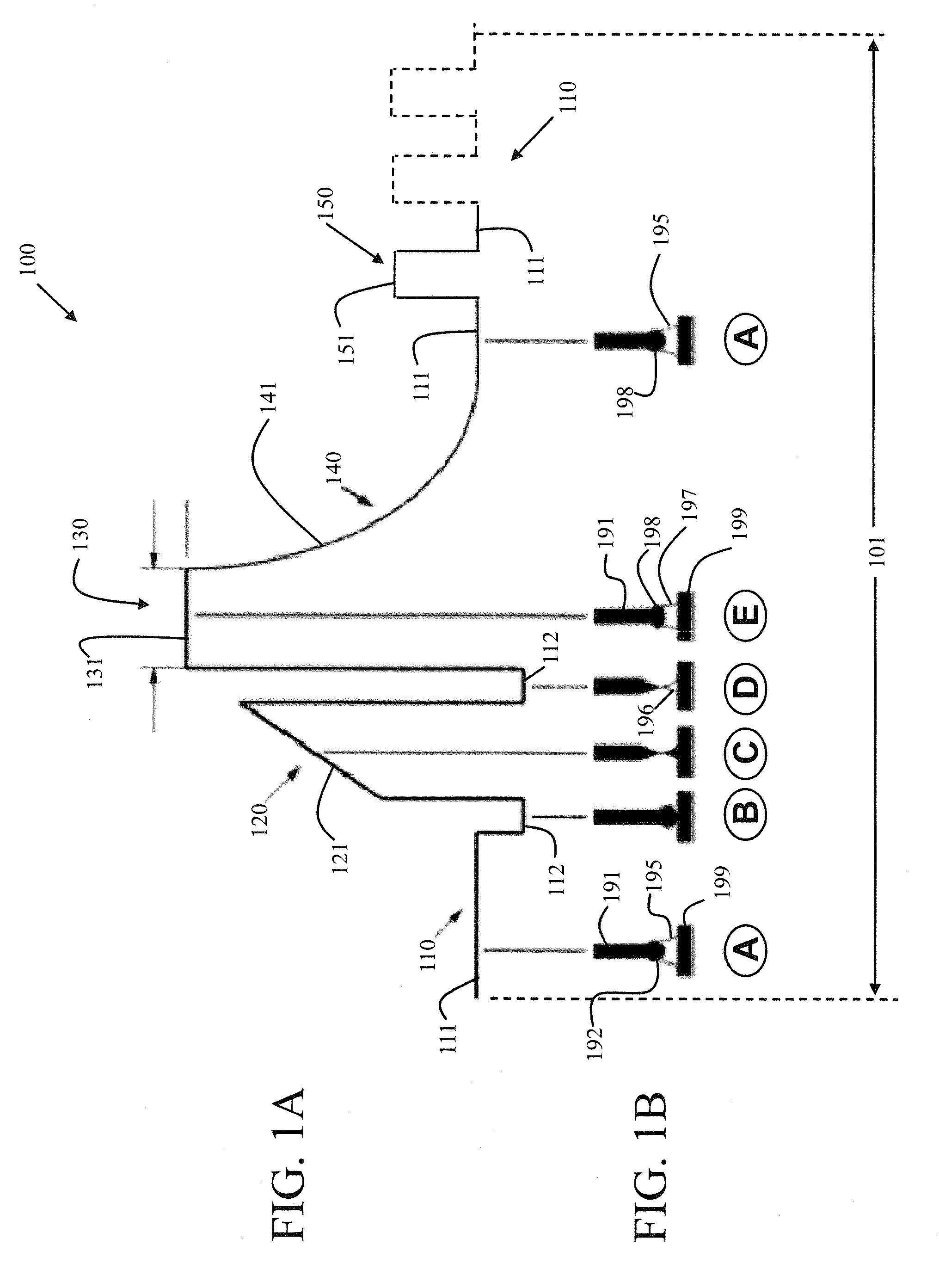
[0022]FIG. 1A illustrates an exemplary embodiment of a cycle 101 of an electric welding waveform 100 used in an arc welding process to increase heat input to a weld. FIG. 1B illustrates the various stages (A-E) of the arc welding process over the cycle 101 using the electric welding waveform of FIG. 1A, showing the relationship between a welding electrode 191 and a metal workpiece 199. During an arc welding process, a series of electric arc pulses are generated between the advancing electrode 191 and the metal workpiece 199 using an electric arc welding system capable of generating the electric welding waveform 100 to produce the electric arc pulses. In general, the cycle 101 periodically repeats during the arc welding process to produce the resultant weld. However, the cycle 101 may repeat without the same number of heat increasing pulses 150 and possibly without a pinch current phase 120 if a short condition does not occur.

[0023]The cycle 101 of the electric welding waveform 100 i...


PUM

PropertyMeasurementUnit
Vickers hardnessaaaaaaaaaa
Speedaaaaaaaaaa
Currentaaaaaaaaaa

Abstract

A method and a system for forming a root pass weld for a root pipe joint. A substantially periodic electric welding waveform is generated and a series of electric arc pulses are generated between an advancing welding electrode and a root pipe joint in response to the electric welding waveform. The electric welding waveform includes a base cycle having a background current phase providing a background current level, a peak current phase providing a peak current level, a tail-out current phase providing a decreasing tail-out current level, and at least one heat-increasing current pulse during the background current phase providing a heat-increasing current level being above the background current level.

Description

CROSS-REFERENCE TO RELATED APPLICATIONS / INCORPORATION BY REFERENCE[0001]This U.S. patent application is a continuation-in-part (CIP) of U.S. patent application Ser. No. 12 / 163,047 filed on Jun. 27, 2008 which is incorporated herein by reference in its entirety.[0002]U.S. Pat. No. 4,972,064, issued on Nov. 20, 1990, is incorporated herein by reference in its entirety. U.S. Pat. No. 6,051,810, issued on Apr. 18, 2000, is incorporated herein by reference in its entirety. U.S. Pat. No. 6,498,321, issued on Dec. 24, 2002, is incorporated herein by reference in its entirety. U.S. patent application Ser. No. 11 / 861,379 filed on Sep. 26, 2007 is incorporated herein by reference in its entirety.TECHNICAL FIELD[0003]Certain embodiments relate to electric arc welding. More particularly, certain embodiments relate to a method of increasing heat input to a weld during a gas metal arc welding (GMAW) short-circuit arc process.BACKGROUND[0004]Open root welding is used for pipe and single-sided plat...

Claims


Application Information

Patent Timeline
IPC IPC(8): B23K9/09
CPCB23K9/0282B23K2201/06B23K9/092B23K2101/06
Inventor DOYLE, THOMAS EDWARDNOEL, CLYDE DAVIDBREAUX, TERRY LOUISPETERS, STEVEN R.
Owner LINCOLN GLOBAL INC
Why Eureka
Try Eureka