Rail arrangement for guiding a fitting inside guiding rails particularly in aircrafts

a technology for guiding fittings and guiding rails, which is applied in the direction of seating arrangements, furniture parts, suspension devices, etc., can solve the problems of ensuring unproblematic and fast displacement of fittings in guiding rails, and achieve the effects of reducing the adhesion force of dirt, reducing the production process, and being more economical

Inactive Publication Date: 2009-12-31
AIRBUS OPERATIONS GMBH
View PDF16 Cites 11 Cited by
  • Summary
  • Abstract
  • Description
  • Claims
  • Application Information

AI Technical Summary

Benefits of technology

[0025]The bead of the guiding rail may extend along the entire length of the guiding rail. This continuous bead along the entire length of the guiding rail may make it possible to keep the production process simpler and thus more economical. If the guiding rail is, for example, made of aluminium, the guiding rail can be produced in an extrusion moulding process.
[0026]In another exemplary embodiment of the invention the bead, the rail base and / or the bottom surface with the groove of the fitting comprise / comprises a friction-reducing surface. Firstly, a friction-reducing surface may make it possible for the force exerted for displacing the displaceable elements to be less when compared to a surface that is not designed so as to be friction-reducing. Moreover, such a surface may reduce the adhesion forces of the dirt. In order to be able to manually displace a displaceable element, it may become necessary to remove from the rail base the dirt that has been collected in the guiding rail, in particular if an excessive amount of dirt has lodged in the guiding rail and said dirt cannot be driven over by the fitting. In such a case the surface mentioned prevents a situation in which for manual displacement of the displaceable elements an operator has to exert increased force.
[0027]Any reduction in the adhesive forces between the dirt and the friction-reducing surface has a particularly advantageous effect in the case of drinks containing a lot of sugar, for example lemonade, because any sugar of such drinks that has crystallised out between the elevation or the bead of the guiding rail and the groove of the fitting, in the absence of a friction-reducing surface can quasi result in sticking of the fitting to the guiding rail. In order to subsequently design the fitting so that it is displaceable relative to the guiding rail, an additional, avoidable, work step would have to be carried out.
[0028]In order to bring about a reduction in friction and a reduction in the adhesive forces, the rail base with the bead or with the elevation of the guiding rail, as well as the groove base, and in addition the bottom surface of the fitting, can, for example, be coated with PTFE or PVDF. Furthermore, it is possible to significantly increase the surface hardness of the material, e.g. aluminium, from which the guiding rails are made, for example by hard-anodising. In addition, such a coating is associated with an advantage in that the pores that have arisen can be closed in a Teflon application method. The bottom surface of the fitting with the groove, which fitting as a rule is made from steel, can in a friction-reducing way comprise, for example, a chromium coating which can also subsequently be given a Teflon coating.

Problems solved by technology

This may ensure unproblematic and fast displacement of the fitting in the guiding rail.

Method used


Image

  • Rail arrangement for guiding a fitting inside guiding rails particularly in aircrafts
  • Rail arrangement for guiding a fitting inside guiding rails particularly in aircrafts
  • Rail arrangement for guiding a fitting inside guiding rails particularly in aircrafts

Examples


Embodiment Construction

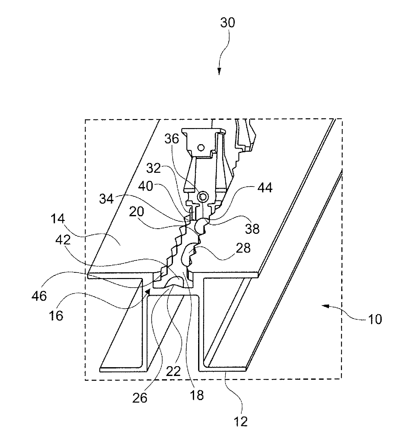
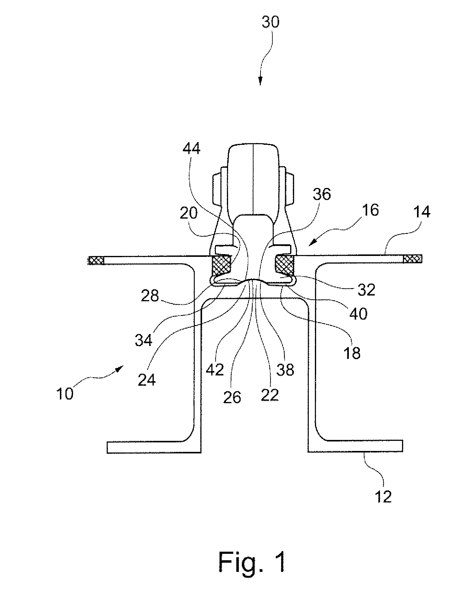
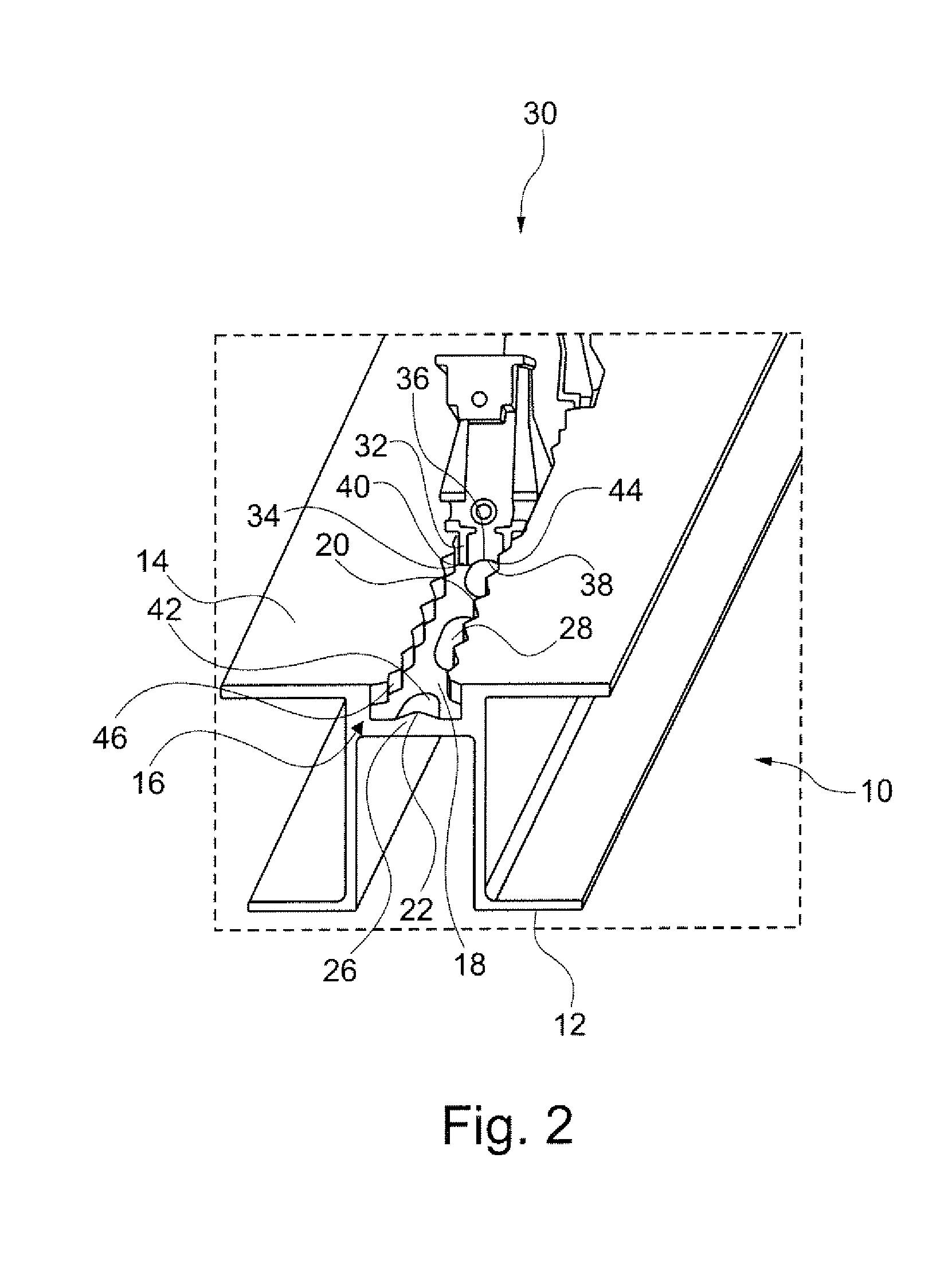
[0035]Identical or similar components in different figures have the same reference characters. The illustrations in the figures are diagrammatic and not to scale.

[0036]FIG. 1 shows a cross section of a rail arrangement according to an exemplary embodiment of the invention with a guiding rail 10 and a fitting 30. The guiding rail 10 comprises a bottom 12 that is rigidly connected to a support structure (not shown in the diagram). Opposite the bottom 12 of the guiding rail 10 there is the top 14. At its middle, the top 14 of the guiding rail 10 is interrupted by a hollow profile 16. The hollow profile 16 extends so as to be flush with the top 14 of the guiding rail 10. There are thus no projections on the top 14 through the hollow profile 16. The bottom of the hollow profile 16 is formed by a rail base 18. In the middle along the guiding rail 10 the hollow profile 16 is open towards the top 14 by a groove-shaped opening 20. In the middle of the rail base 18 and along the guiding rail ...


PUM


Abstract

The invention relates to a rail arrangement for coupling a displaceable element to a support structure, wherein the rail arrangement comprises a guiding rail and a fitting. In this arrangement the fitting is connectable to the displaceable element, and the guiding rail is connectable to the support structure. The fitting is arranged in the guiding rail in such a way that the fitting can be displaced in longitudinal direction of the guiding rail; wherein the guiding rail is formed as an open-top hollow profile with a rail base. In this arrangement the rail base comprises at least one elevation that extends upwards (i.e. towards the open-top). The fitting comprises a bottom surface which in longitudinal direction is interrupted by a continuous groove, wherein the form of the groove of the fitting is designed in such a way that the fitting is guided by the elevation along the guiding rail.

Description

CROSS-REFERENCE TO RELATED APPLICATIONS[0001]This application claims the benefit of the filing date of U.S. Provisional Patent Application No. 61 / 133,479 filed Jun. 30, 2008, the disclosure of which is hereby incorporated herein by reference.BACKGROUND OF THE INVENTION[0002]The present invention relates to a rail arrangement for guiding fittings inside guiding rails, particularly in aircraft, as well as to an aircraft comprising such a rail arrangement.[0003]In most commercial aircraft the seat rows for passengers are arranged in the fuselage in such a way that the passengers are seated in the direction of flight, wherein the individual seat rows extend transversely to the direction of flight, and wherein several seat rows are arranged one behind the other in the direction of the longitudinal axis of the aircraft. Seat rows comprising two or three seats side-by-side are the norm. In larger aircraft, which most of the time can also comprise wider fuselages, in the meantime seats may ...

Claims


Application Information

Patent Timeline
Patent Type & Authority Applications(United States)
IPC IPC(8): B64D11/06F16M13/02
CPCB64C1/18B60N2/01575
Inventor WILHELM, ARNEFRITZ, MARKUS
Owner AIRBUS OPERATIONS GMBH
Why Eureka
Try Eureka