Heat dissipation apparatus having a fan received therein

a technology of heat dissipation apparatus and fan, which is applied in the direction of insulated conductors, power cables, cables, etc., can solve the problems of affecting the assembly and affecting the performance of the heat dissipation apparatus

Inactive Publication Date: 2009-12-31
FU ZHUN PRECISION IND SHENZHEN +1
View PDF7 Cites 5 Cited by
  • Summary
  • Abstract
  • Description
  • Claims
  • Application Information

AI Technical Summary

Problems solved by technology

It is well known that if heat generated by electronic components, such as integrated circuit chips, during operation is not efficiently dissipated, these electronic components may suffe

Method used


Image

  • Heat dissipation apparatus having a fan received therein
  • Heat dissipation apparatus having a fan received therein
  • Heat dissipation apparatus having a fan received therein

Examples


Embodiment Construction

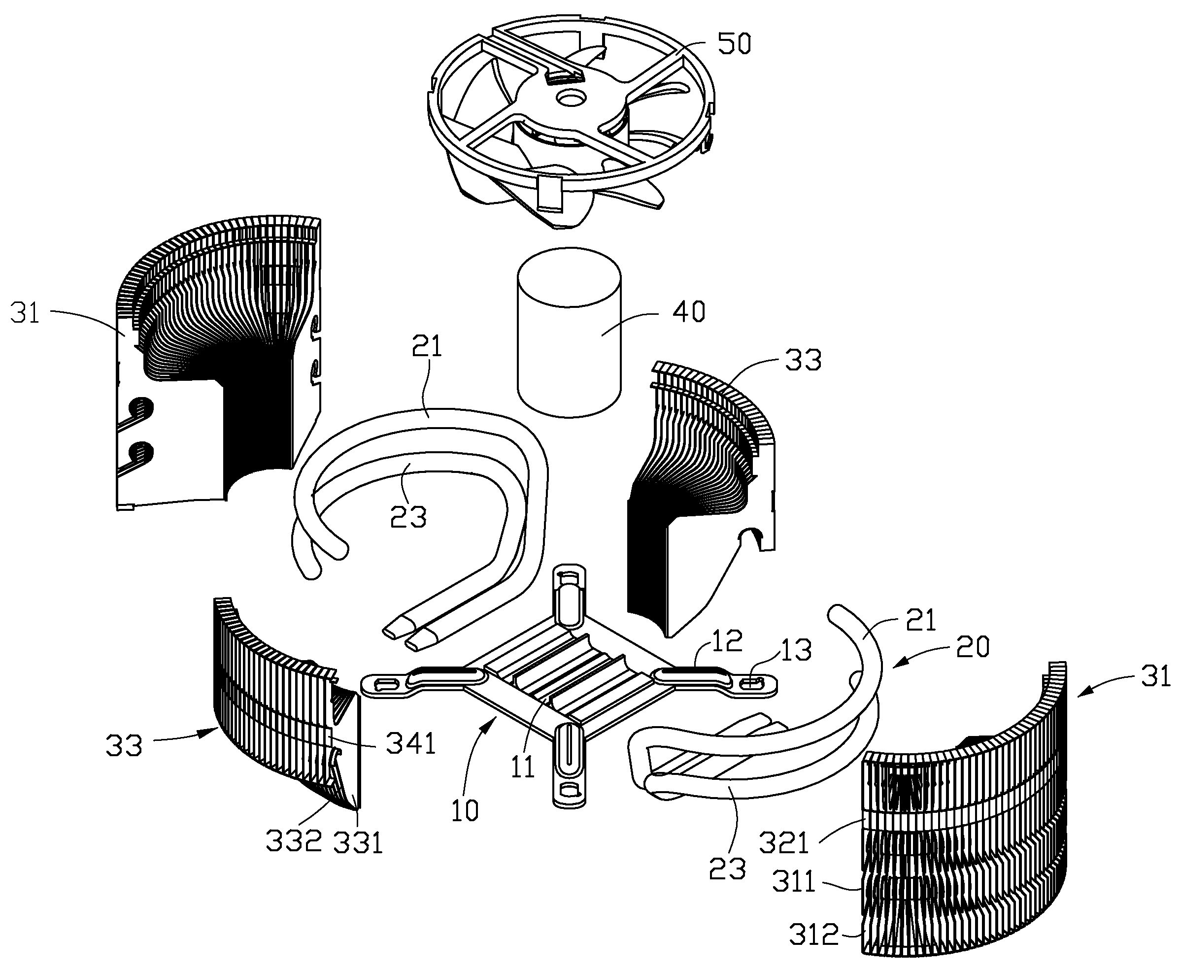
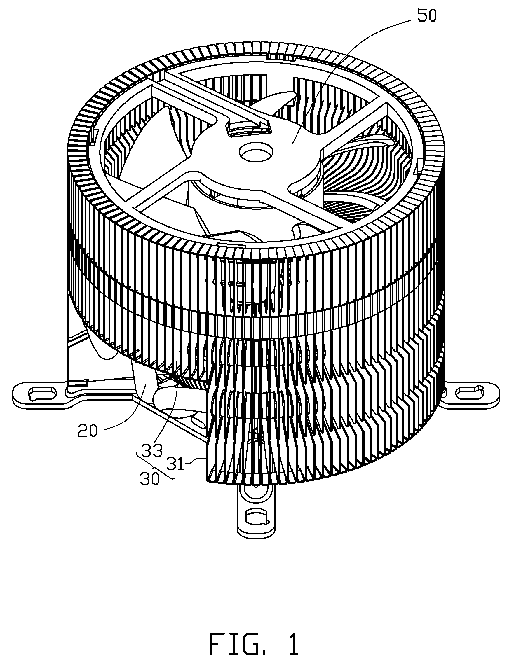
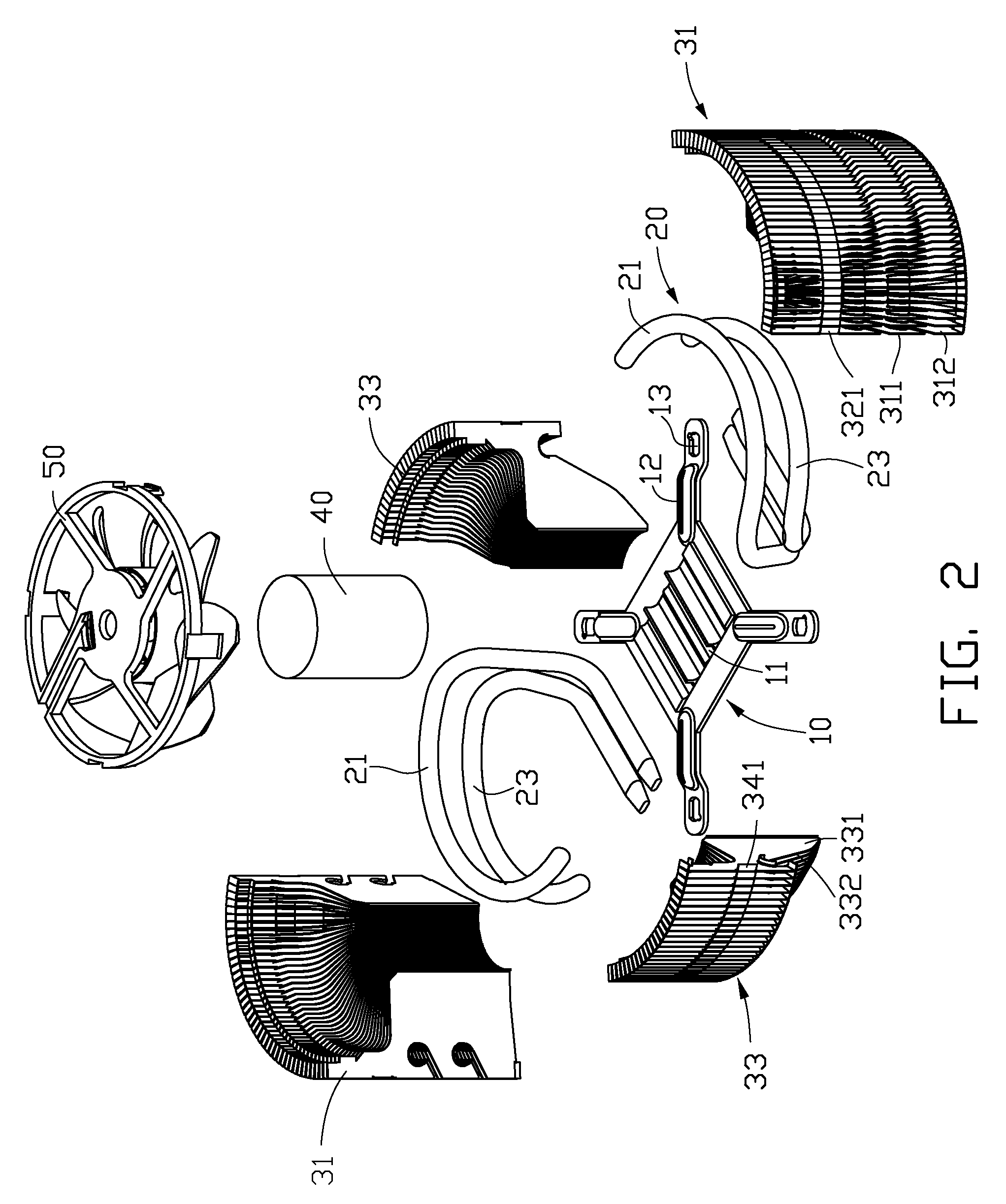
[0018]Referring to FIGS. 1 and 2, a heat dissipation apparatus in accordance with a first embodiment of the disclosure is shown. The heat dissipation apparatus includes a base 10, a heat sink 30, a heat pipe assembly 20 thermally connecting the base 10 with the heat sink 30, a cylindrical heat conductive core 40 received in the heat sink 30, and a fan 50 mounted in a top of the heat sink 30.

[0019]The base 10 is a metal plate, and has a high heat conductivity. Preferably, the base 10 is made of copper. The base 10 thermally connects with a heat generating electronic component at a bottom surface thereof, and attaches to the heat pipe assembly 20 at a top surface thereof. A number of grooves 11 are defined in the top surface of the base 10 for accommodating the heat pipe assembly 20. In this embodiment, the base 10 defines four parallel grooves 11 thereon. A securing arm 12 extending outwardly from each corner of the base 10 defines a securing hole 13 therein for assembly of the heat ...


PUM


Abstract

A heat dissipation apparatus includes a heat sink and a fan. The heat sink defines a recessed space at a center of a top end thereof, and an engaging groove in an inner circumference of the top end of the heat sink surrounding and communicating with the space. The fan includes a frame and an impeller assembled to the frame. A plurality of legs extends downwardly from the frame. Each of the legs includes a hook at a free end thereof. The hooks of the legs engage in the engaging groove of the heat sink for securely mounting the fan in the recessed space of the heat sink. Heat pipes extend through the heat sink and connect with a base.

Description

CROSS-REFERENCE TO RELATED APPLICATION[0001]This application is related to a co-pending application entitled “HEAT DISSIPATION APPARATUS HAVING HEAT PIPES INSERTED THEREIN” (attorney docket number US 20113), assigned to the same assignee of this application and filed on the same date. The disclosure of the co-pending application is wholly incorporated herein by reference.BACKGROUND[0002]1. Technical Field[0003]The disclosure generally relates to heat dissipation, and particularly to a heat dissipation apparatus utilizing a fan for dissipating heat generated by electronic components.[0004]2. Description of Related Art[0005]It is well known that if heat generated by electronic components, such as integrated circuit chips, during operation is not efficiently dissipated, these electronic components may suffer damage. Thus, heat dissipation apparatuses are often used to cool the electronic components.[0006]A typical heat dissipation apparatus includes a heat sink and a fan. The heat sink...

Claims


Application Information

Patent Timeline
IPC IPC(8): H05K7/20
CPCH01L23/427H01L23/467H01L2924/0002H01L2924/00
Inventor DENG, HONG-BOZHAO, DI-QIONGCHEN, YE
Owner FU ZHUN PRECISION IND SHENZHEN
Why Eureka
Try Eureka