High pressure pre-burst for improved fluid delivery

a high-pressure, fluid-delivering technology, applied in the field of high-pressure pre-burst for improving fluid-delivering, to achieve the effect of little rise and fall times

Active Publication Date: 2009-12-31
ULTHERA INC
View PDF106 Cites 53 Cited by
  • Summary
  • Abstract
  • Description
  • Claims
  • Application Information

AI Technical Summary

Benefits of technology

[0011]A group of interleaved functions may be provided including a high-pressure burst, a solution infusion, and a treatment. The group may be performed one or more times. The high pressure burst is represented by injecting the treatment solution and the treatment includes injecting a third solution or applying an energy to the treatment area, and the high pressure burst is timed to a pressure function, the solution infusion is timed to an infusion function, and the treatment is timed to a treatment function, wherein each function is rectangular in shape with little rise and fall times. Alternatively, the high-level burst may be performed first, followed by a group of interleaved functions including the solution infusion and the treatment.

Problems solved by technology

Although these fibrous structures do not necessarily isolate neighboring chambers, localized pockets are nevertheless created by the structures and fluid flow is substantially restricted to the chamber proximate the injection site.

Method used


Image

  • High pressure pre-burst for improved fluid delivery
  • High pressure pre-burst for improved fluid delivery
  • High pressure pre-burst for improved fluid delivery

Examples


Embodiment Construction

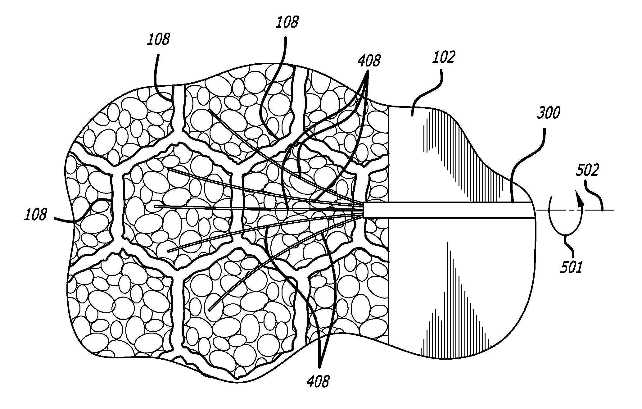
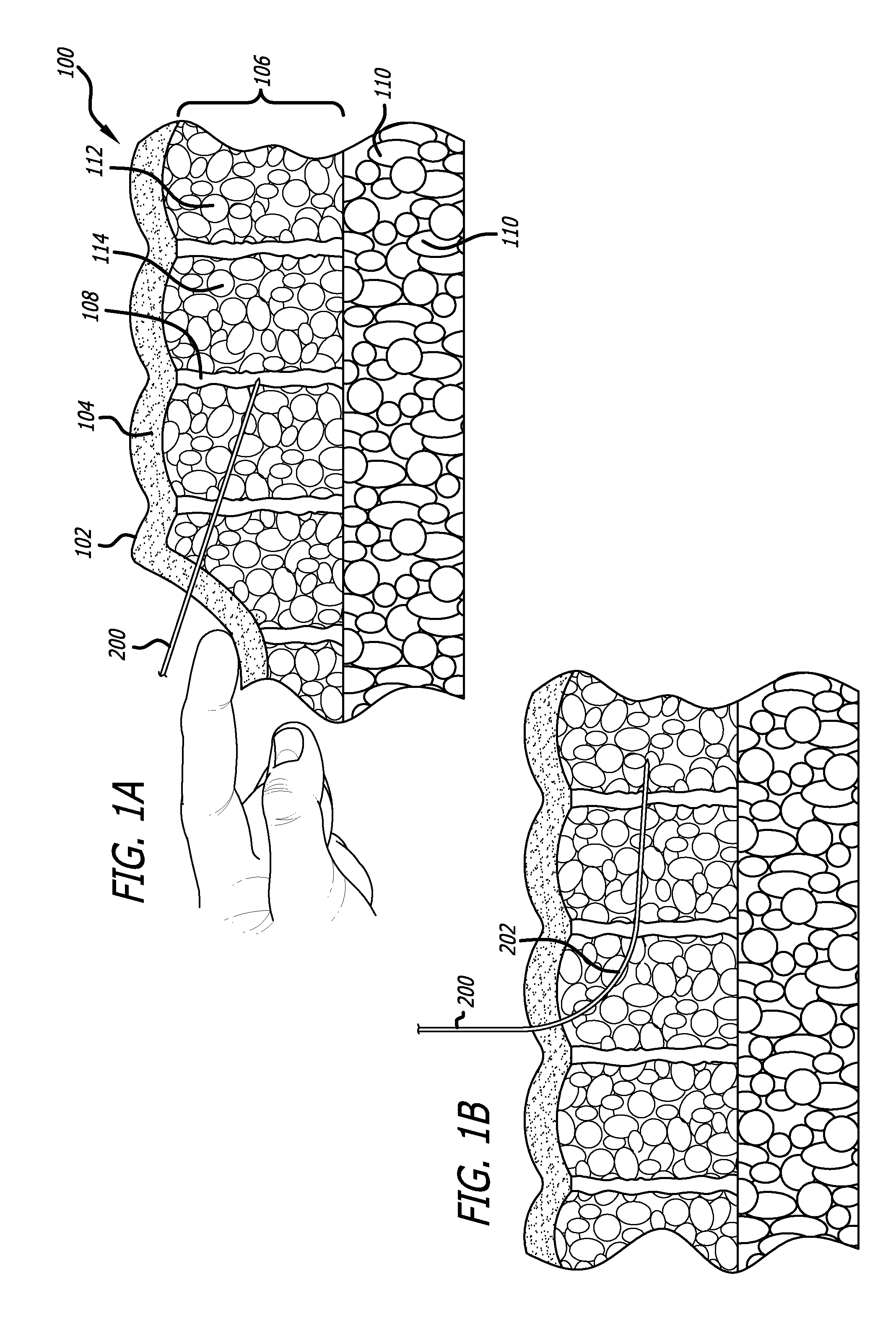
[0023]Referring first to FIGS. 1A and 1B, a cross section of a portion of a normal subcutaneous tissue region 100 is shown, including the epidermis 102, dermis 104, subcutaneous fat 106, fibrous septae 108, and deeper fat layers 110. The subcutaneous tissue also includes vascularity, microcirculation, and lymph drainage. The dermis interfaces with the fatty subcutaneous connective tissue that attaches to the dermal layers via substantially vertical septae 108 (collagenous fibers). The subcutaneous fatty tissue 106 is compartmentalized into chambers 112 of adipose tissue (fat) separated by the fibers of the septae. These chambers can increase in size due to the presence of increased adipocytes (fat cells) 114 or swell due to retained fluid. The increase in chamber size may cause tension on the septae and ultimately dimpling at the epidermal surface as the fatty regions swell and the septae thicken under the tension. Microcirculation and lymphatic drainage may then become impaired, fu...


PUM


Abstract

A needle with multiple injection ports is used in connection with a high-pressure injection system to infuse a treatment solution into a treatment area below the dermis of the skin. The needle has multiple tines that extend outwardly from the injection ports while inside the treatment area to disrupt tissue in the treatment area and to create multiple pathways of infusion. The tines are withdrawn and the needle is partially withdrawn, and solution is injected from the needle into the treatment area at high pressure to infuse the tissue within the treatment area. The burst, infusion, and a treatment such as an energy or third solution may be interleaved and repeated multiple times.

Description

CROSS-REFERENCES TO RELATED APPLICATIONS[0001]This application is a continuation-in-part and claims priority from U.S. application Ser. No. 11 / 515,634, filed Sep. 5, 2006, and from U.S. application Ser. No. 11 / 334,794, filed Jan. 17, 2006, now U.S. Pat. No. 7,588,547, both of which are incorporated by reference in their entirety.BACKGROUND[0002]It has been discovered that the prominence of fibrous septae within the immediate subdermal layers restricts fluid permeability between respective chambers of fat cells. Although these fibrous structures do not necessarily isolate neighboring chambers, localized pockets are nevertheless created by the structures and fluid flow is substantially restricted to the chamber proximate the injection site. It has been further discovered that these structures are not generally impermeable to a fluid. Accordingly, it has been discovered that a substantial amount of pressure utilizing the device and method herein described will penetrate neighboring cha...

Claims


Application Information

Patent Timeline
Patent Type & Authority Applications(United States)
IPC IPC(8): A61M5/00A61N1/30A61B17/32A61H1/00
CPCA61B18/1402A61H2207/00A61B2018/0016A61B2018/00452A61B2018/143A61B2018/1432A61B2218/002A61H23/0245A61H2201/0207A61H2201/10A61H2201/105A61N1/327A61N2005/0661A61N2007/0008A61B18/1477
Inventor CHOMAS, JAMES E.DEEM, MARK E.GIFFORD, HANSON S.SUTTON, DOUGLAS S.
Owner ULTHERA INC
Why Eureka
Try Eureka