
Systems and methods for inserting a bone anchor without a pilot hole

Inactive Publication Date: 2009-12-31
AMEDICA A DELAWARE
View PDF7 Cites 57 Cited by
  • Summary
  • Abstract
  • Description
  • Claims
  • Application Information

AI Technical Summary

Benefits of technology

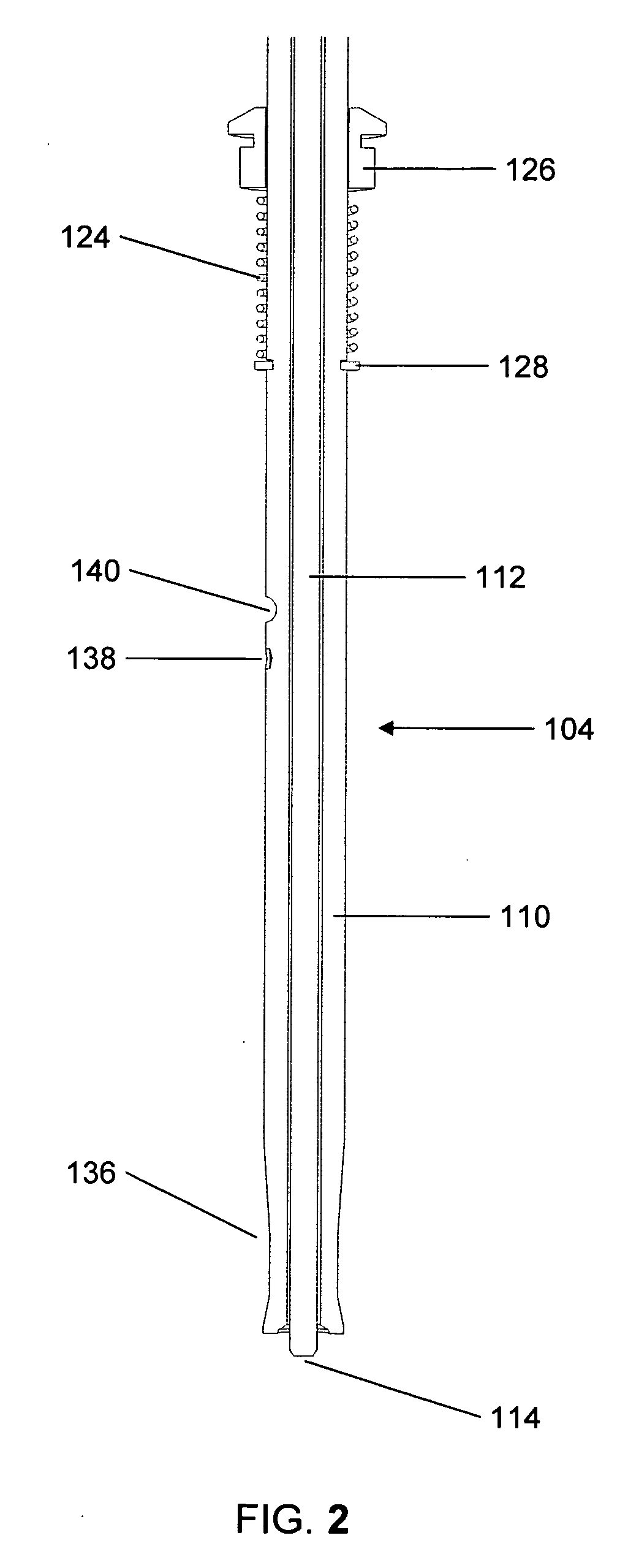
[0013]In some embodiments, the rod and the housing member may share a longitudinal axis along which the rod and housing member can move relative to each other, for example, to permit loading and unloading of the bone anchor within the housing member and to allow the bone anchor to be visible to a surgeon as it is advanced into bone. The distal end of the housing member may be configured to be seated within a bore of a bone fixation plate and secured in place by, for example, a press-fit. Advancement of a handle rigidly coupled (e.g., by welding) to a proximal end of the rod may cause the bone screw to advance into bone.
[0016]In some embodiments, the bone anchor insertion assembly includes a mechanism for facilitating positioning and / or movement of the housing member relative to the rod. For example, in some embodiments, the housing member may include a ball detent that is configured for receipt within a complimentary recess in the rod. When the housing member is advanced distally relative to the rod, the ball detent may be seated within the complimentary recess thus fixing a relative position of the housing and the rod. In this position, the housing member may serve as a guide for insertion of the bone anchor through a bone fixation plate and into bone.

Problems solved by technology

For example, trauma frequently results in damage at the upper end of the lumbar spine, where the mobile lumbar segments join the less mobile dorsal spine.
Excessive forces on the spine not only produce life-threatening traumatic injuries, but may contribute to an increased rate of degenerative change.
Because the neck has a wide range of motion and is the main support for the head, the neck is extremely vulnerable to injury and degeneration.
However, these screws normally are not used in practice without a pilot hole.
If the screw is placed off center, the threads may interfere with or damage a locking mechanism of the bone plate or the screw head may not sit flush inside the screw bore.
However, the present inventor notes that the use of a separate bone awl to create a pilot hole adds extra steps, complexity and time to the surgical procedure.
However, the present inventor notes that the use of a separate drill to create a pilot hole adds extra steps, complexity and time to the surgical procedure.
Further, throughout the advancement of the screw until or just before the screw head is seated within the bone plate, the guide post remains within the screw bore of the cervical plate, thus limiting the ability of a surgeon to visually monitor the procedure.

Method used


Image

  • Systems and methods for inserting a bone anchor without a pilot hole
  • Systems and methods for inserting a bone anchor without a pilot hole
  • Systems and methods for inserting a bone anchor without a pilot hole

Examples


Embodiment Construction

[0038]Embodiments of the present invention relate to assemblies and methods for inserting a bone anchor (e.g., bone screw) into bone. Advantageously, the assemblies and methods described herein can alleviate the need to create a pilot hole in the bone, thus allowing for a reduction in the complexity of and time required for the surgical procedure.

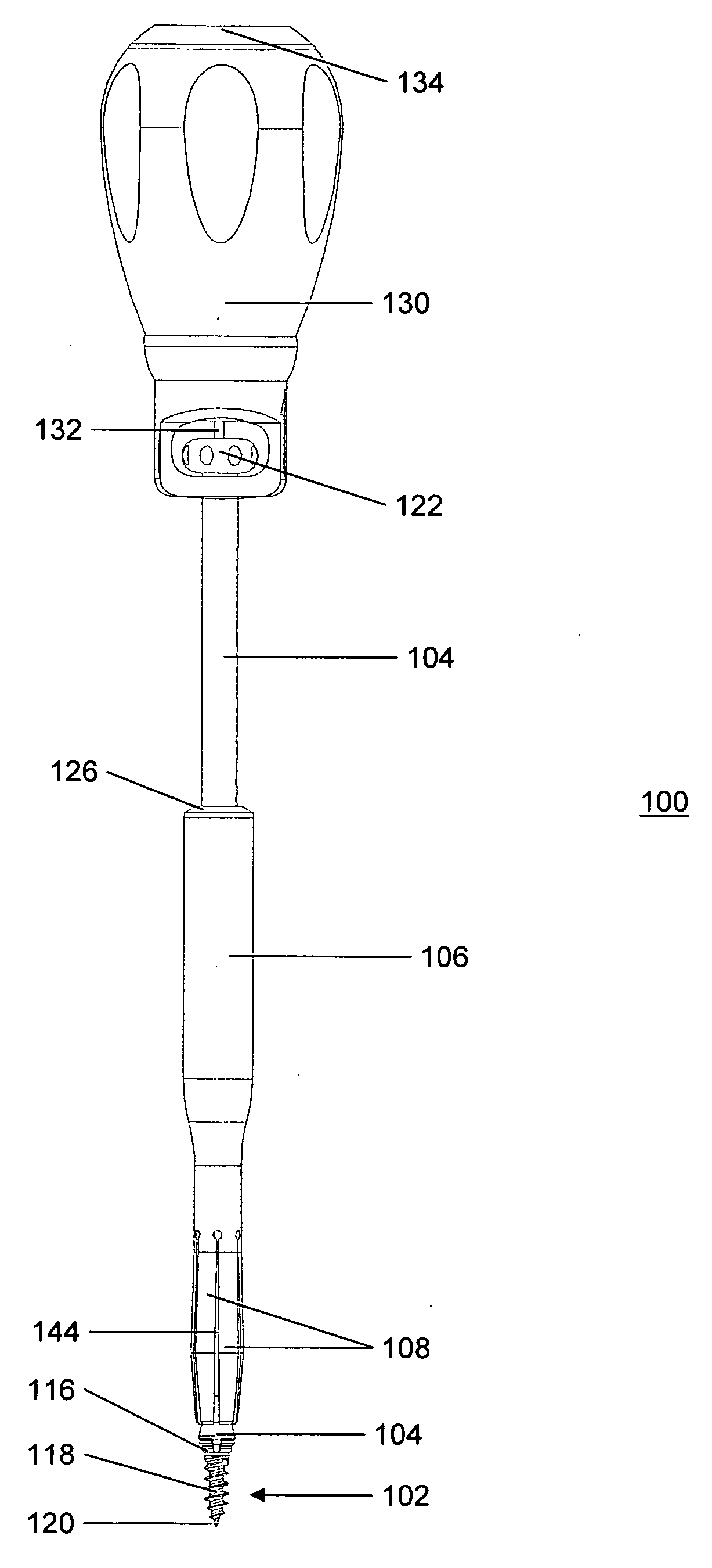
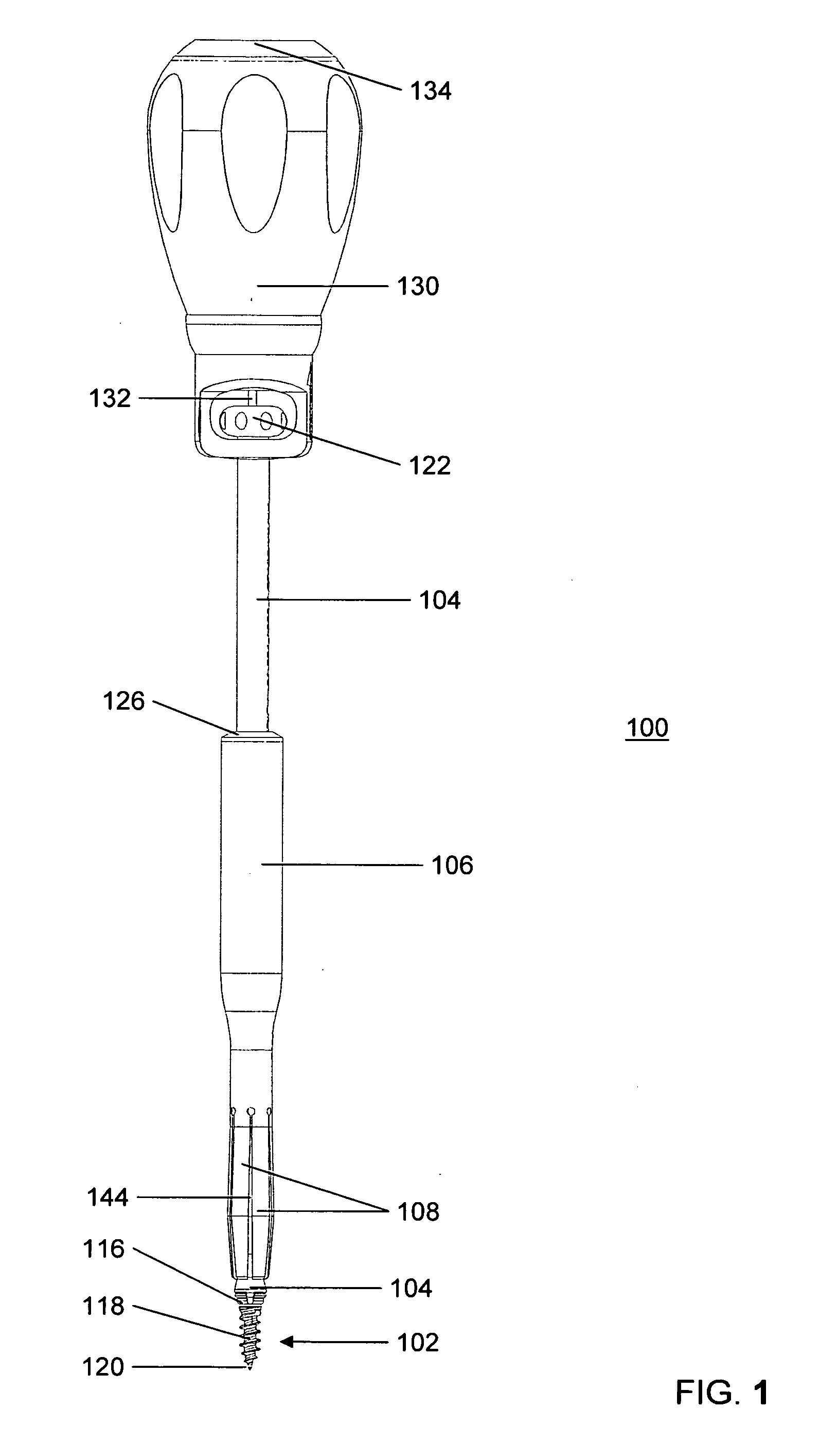
[0039]FIG. 1 is a side view of a bone anchor insertion assembly 100 according to some embodiments of the present invention. Assembly 100 includes bone anchor 102, rod 104 and housing member 106. In some embodiments, housing member 106 is a sleeve, for example, a sleeve (e.g., elongated sleeve) with a circular or oval circumference. At the distal or screw receiving end of housing member 106 is a flexible portion capable of flexing in a direction away from a longitudinal axis of housing member 106. In some embodiments, the flexible portion of housing member 106 includes one or more (e.g., four, five or six) flexible members, for example, flex...


PUM


Abstract

Bone anchor insertion assemblies and methods are provided for inserting a bone anchor (e.g., bone screw) into bone without having to create a pilot hole. In some embodiments, the assembly includes a bone anchor, a housing member, and a rod. The housing member, which is coupled to the rod, is movable between proximally and distally advanced positions relative to the rod. In the proximal position, the bone anchor can be coupled to the rod. In the distal position, a tip of the bone anchor is generally aligned with a distal end of the housing member. The bone anchor is advanced into the bone under guidance of the housing member, where the tip of the bone anchor serves as a bone awl. Once the bone anchor is seated within the bone, the housing member can be returned to the proximal position to improve visibility of the surgical procedure.

Description

FIELD OF THE INVENTION [0001]Embodiments of the present invention relate to bone anchor insertion assemblies and tools that can be used to insert a bone anchor (e.g., bone screw) into a bone without having to create a pilot hole. Other embodiments of the present invention relate to methods for inserting a bone anchor into a bone without having to create a pilot hole.BACKGROUND OF THE INVENTION [0002]The spine is a flexible, multi-segmented column that supports upright posture in a human while providing mobility to the axial skeleton. The spine encases and protects vital neural elements while providing structural support for the body by transmitting the weight of the body through the pelvis to the lower extremities. The cervical spine exhibits a wide range of motion due to the orientation of its facets and the lack of supporting structures. The thoracic and lumbar regions of the spine also have significant ranges of motion.[0003]The spine is made up primarily of bone and intervertebr...

Claims


Application Information

Patent Timeline
IPC IPC(8): A61B17/58B25B13/48
CPCA61B17/8891B25B15/02B25B23/101B25B23/0064B25B23/005
Inventor SCHAFFHAUSEN, CORY R.
Owner AMEDICA A DELAWARE
Learn More