Stator manufacturing apparatus and method for rotary electric machines

a technology of stators and manufacturing methods, which is applied in the manufacture of tools, metal working apparatus, dynamo-electric components, etc., can solve the problems of increasing the axial dimension of stators, difficult to assemble such a cylindrical cage-shaped stator coil into an integral type stator core, and difficult to assemble stator cores. achieve the effect of uniform diameter and easy and evenly performing radial shrinkag

Active Publication Date: 2010-01-07
DENSO CORP
View PDF6 Cites 16 Cited by
  • Summary
  • Abstract
  • Description
  • Claims
  • Application Information

AI Technical Summary

Benefits of technology

[0012]The present invention has been made in light of the circumstances described above, and has as its object to provide a resolution for easily and evenly performing radial shrinkage of a stator core in which segment cores are disposed along the circumference, so that a uniform diameter can be obtained for the stator core.
[0017]Without the heat insulating member, the tapered guide unit, when coming into contact with the heating unit, will be heated and thermally expanded, disabling reduction in the diameter of the stator core to a desired smallness. On the other hand, the heat insulating member, if provided, can suppress the heat from the heating unit from being transferred to the tapered guide unit when the tapered guide unit comes into contact with the heating unit. Therefore, the diameter of the stator core can be reliably reduced to a desired size without thermally expanding the tapered guide unit, in a configuration where the tapered guide unit comes into contact with the heating unit for smooth insertion of the stator core into the outer cylinder.
[0020]In this regard, the pressing units, if provided, can suppress the radial expansion of the stator core when the stator core is inserted into the outer cylinder. Thus, the electromagnetic steel plates can be prevented from being peeled off or from suffering from any damage, when the stator core is inserted into the through hole or into the outer cylinder.
[0022]According to the present invention, the outer diameter of the stator core is reduced by permitting the stator core to pass on and along the taper of the through hole formed in the tapered guide unit. Thus, a uniform diameter can be obtained throughout the stator core. In particular, the circularity (which is expressed by the difference between the radius of a maximum incircle and that of a minimum circumcircle) of the stator core in terms of its inner diameter can be reduced to 0.05 mm or less.

Problems solved by technology

This however has raised a problem of increasing the axial dimension of stators.
However, it is quite difficult to assemble such a cylindrical cage-shaped stator coil into an integral type stator core already having a shape of a core.
Otherwise, the stator core will be distorted and thus the circularity (e.g., 0.05 mm) required for a rotary electric machine cannot be ensured.
Since the stator core in fact has been divided along the circumference, it is difficult to evenly shrink the stator core.
Thus, segment cores have created a problem of difficulty in achieving shrinkage fitting with a uniform diameter throughout the stator core.

Method used


Image

  • Stator manufacturing apparatus and method for rotary electric machines
  • Stator manufacturing apparatus and method for rotary electric machines
  • Stator manufacturing apparatus and method for rotary electric machines

Examples


Embodiment Construction

[0049]With reference to the accompanying drawings, hereinafter will be described in detail a stator manufacturing apparatus and a stator manufacturing method, according to an embodiment of the present invention. The embodiment that will be described here is only an example, and thus the stator manufacturing apparatus and the stator manufacturing method of the present invention are not intended to be limited by the embodiment provided below. The stator manufacturing apparatus and the stator manufacturing method of the present invention may be implemented in various modes after being modified and / or improved, for example, by a person skilled in the art within the scope not departing from the spirit of the present invention.

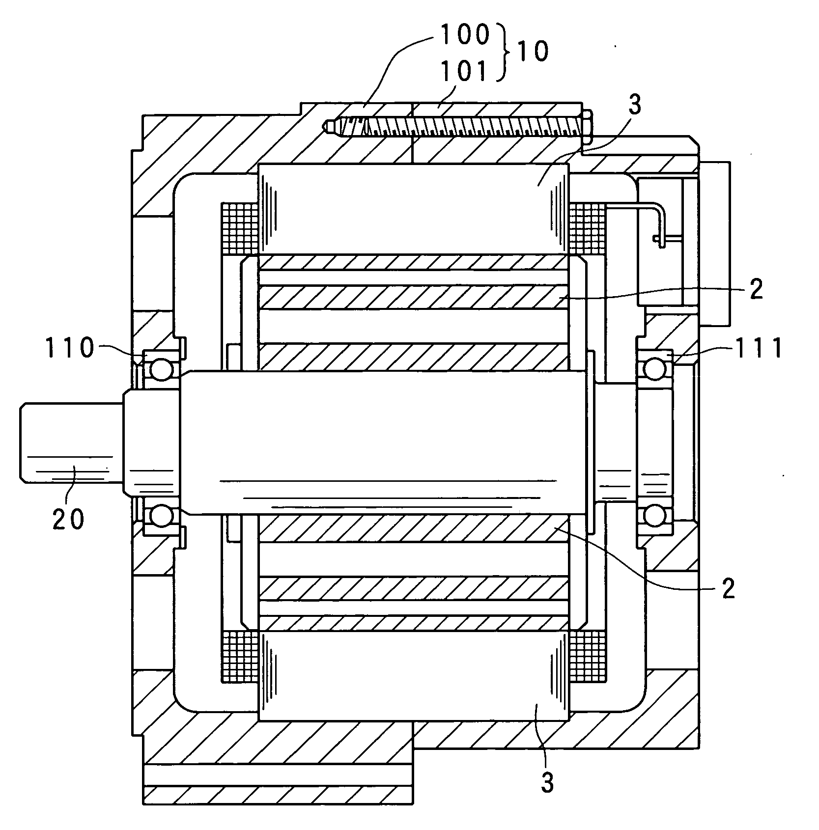
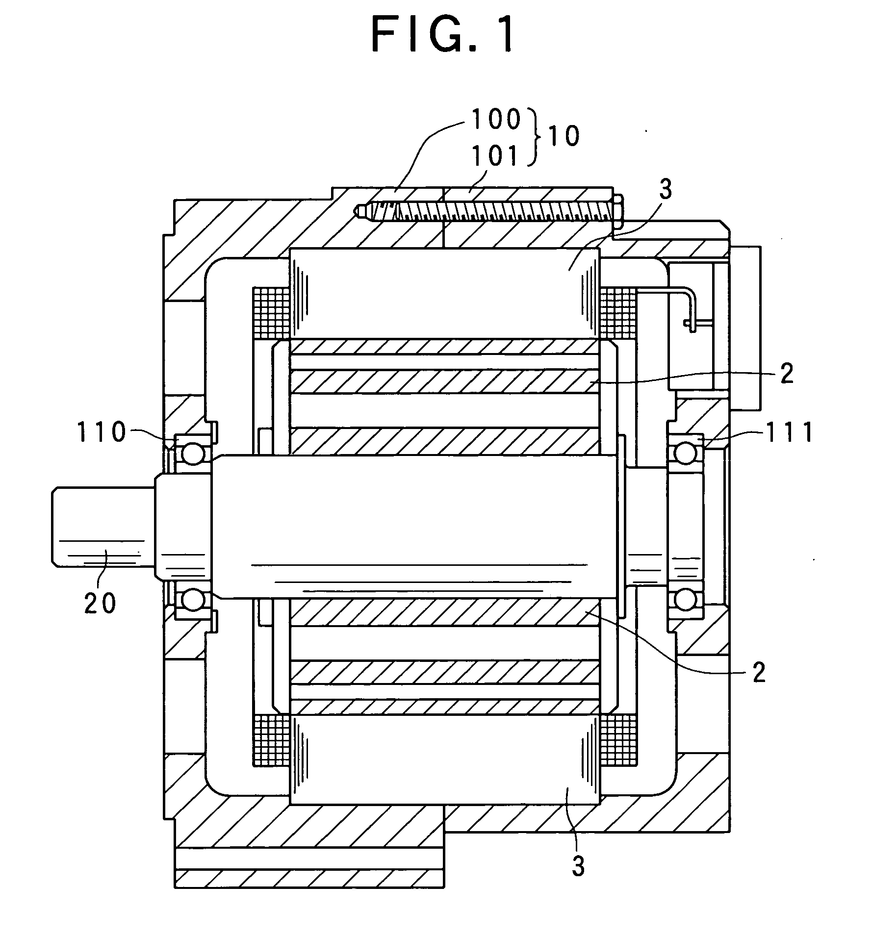
[0050]To begin with, hereinafter is described a configuration of a rotary electric machine 1 using a stator which has been obtained by using a stator manufacturing apparatus and a stator manufacturing method according to the present embodiment.

[0051]As shown in FIG....


PUM

PropertyMeasurementUnit
inner diameteraaaaaaaaaa
thicknessaaaaaaaaaa
taper angleaaaaaaaaaa

Abstract

A method is provided, for manufacturing a stator for a rotary electric machine by shrink-fitting an outer cylinder to a core assembly where a cage-shaped wound coil is assembled with segment cores. The assembly is inserted into the outer cylinder having a diameter increased by thermal expansion caused by the heat from a heating unit, while the outer diameter of the assembly is being reduced by permitting the assembly to pass through a tapered guide unit. The guide unit has a portion whose diameter is larger than an outer diameter of the assembly, and a portion whose diameter is larger than an inner diameter of the outer cylinder and smaller than an inner diameter of the cylinder in the thermally expanded state, and a tapered through hole vertically passing through the guide unit. Thus, the size of the assembly is radially reduced, with a uniform diameter being obtained throughout the assembly.

Description

CROSS-REFERENCE TO RELATED APPLICATION[0001]This application is based on and claims the benefit of priority from earlier Japanese Patent Application No. 2008-177304 filed Jul. 7, 2008, the description of which is incorporated herein by reference.BACKGROUND OF THE INVENTION[0002]1. Field of the Invention[0003]The present invention relates to a stator manufacturing apparatus and a stator manufacturing method for rotary electric machines, and in particular, to a stator manufacturing apparatus and a stator manufacturing method for rotary electric machines, with which the segment cores of a stator to be manufactured are shrink-fitted to an outer cylinder, in manufacturing the stator for a rotary electric machine.[0004]2. Description of the Related Art[0005]In recent years, small size, high power and high quality have been demanded of rotary electric machines used as electric motors and electric generators. Taking rotary electric machines loaded on vehicles as an example, the space for lo...

Claims


Application Information

Patent Timeline
Patent Type & Authority Applications(United States)
IPC IPC(8): H02K15/00
CPCY10T29/53143H02K15/024Y10T29/49009
Inventor AKIMOTO, AKITOMORIGUCHI, KEIGOHAYASHI, SEIJI
Owner DENSO CORP
Why Eureka
Try Eureka