Method of manufacturing hollow body

a manufacturing method and hollow body technology, applied in the field of hollow body manufacturing, can solve the problems of inability to integrally molded flanges and attachment parts, and inability to obtain smooth inner and outer surfaces of bent pipes, etc., to achieve excellent inner surface smoothness, cost reduction, and uniform inner diameter

Active Publication Date: 2012-03-22
RP TOPLA
View PDF1 Cites 31 Cited by
  • Summary
  • Abstract
  • Description
  • Claims
  • Application Information

AI Technical Summary

Benefits of technology

[0015]According to the present invention, it is possible to manufacture, by injection molding, a hollow body formed of a thermoplastic resin and having uniform inner diameter and thickness and an excellent inner surface smoothness, and, in particular, a pipe-shaped hollow body having a bent portion. Further, since the hollow body is formed by the injection molding, various attached complex portions including an attachment portion, a connection portion, and a seal portion can be integrally molded with the hollow body such as a bent pipe, so that cost can be reduced.

Problems solved by technology

However, in the extrusion molding method, a pipe material itself is rigid, and thus a bent pipe having smooth inner and outer surfaces cannot be obtained.
Moreover, a flange portion and an attachment portion cannot be integrally molded to a pipe, and a molded body portion having a coupling function cannot be integrally molded to a pipe end portion.
In the blow molding method, although a three-dimensional bent pipe can be molded by the recent development of a mold tilting mechanism and a multipurpose blow molding machine having a mold swinging apparatus, the thickness accuracy, the surface finishing accuracy, the dimensional accuracy, component integrating function, and so on do not attain a satisfactory level compared to injection molding.
Further, the blow molding method has many problems that the material to be used is limited in terms of characteristics such as the fluidity and the melt viscoelasticity of the materials, and especially engineering plastics are strongly subjected to the above limitations.
However, although a hollow pipe portion can be molded by this method, a uniform inner diameter cannot be secured.
Although there has been known a water assist injection molding (WIT) method of forming the hollow pipe portion with the use of water as a fluid instead of gas (Non Patent Document 1), this method has a problem in the uniformity of a pipe inner diameter, the uniformity of pipe thickness, the smoothness of a pipe inner surface, and so on, and thus there is a limit to the expansion of pipe molding by the injection molding.
However, in order to apply the method to a pipe required to have high strength and high durability, a higher level of uniformity in the pipe inner diameter and the pipe thickness and the smoothness of the pipe inner surface are required, and it is a fact that there is a limit to the increasing use of this method.

Method used


Image

  • Method of manufacturing hollow body
  • Method of manufacturing hollow body
  • Method of manufacturing hollow body

Examples


example 1

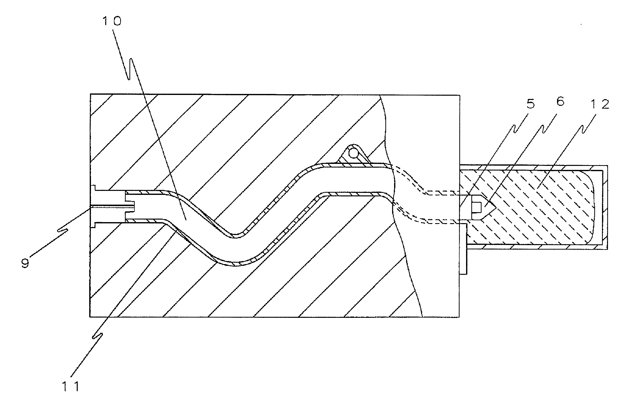
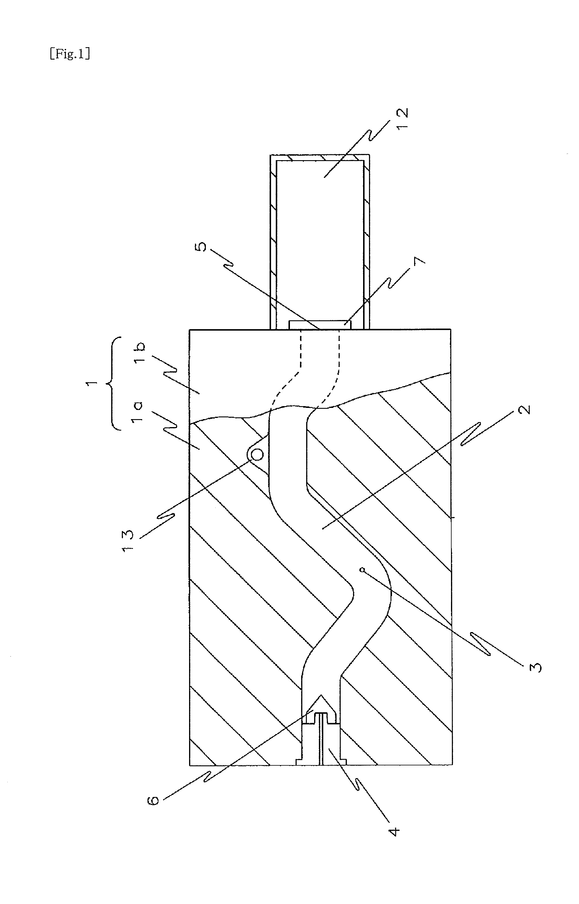
[0048]A bent pipe shown in FIG. 5 in which an attachment portion 13 is integrally formed with a pipe portion 11 (outer diameter is 21 mm, the inner diameter is 16 mm, the thickness is 2.5 mm, and the length is 250 mm) is molded using the mold of FIG. 1.

[0049]As a floating core, the one shown in FIG. 10 is used. The floating core of FIG. 10 is formed of a GF reinforced polyamide 66 resin (“Leona 14G33” manufactured by Asahi Kasei Chemicals Corporation). The diameter (A) of a columnar portion of the floating core is 16 mm, the height (H1) of the columnar portion is 6 mm, and the height (H2) of a conically-shaped top portion of the floating core is 10 mm. The bottom surface of the columnar portion has a recess (the diameter is 6 mm, the depth is 6 mm, and the taper is 3°), and a corner rounding processing with a curvature radius of 1 mm is applied to the peripheral edge of the bottom surface of the columnar portion.

[0050]The GF reinforced polyamide 66 is injected at a resin temperature...

example 7

[0054]A bent pipe is obtained in the same manner as for the embodiment 1 except for using the floating core, which is the same as the floating core of the embodiment 1 except that there is no recess, and the pressure port 4 in plane contact with the floating core 6, as shown in FIG. 11. The results are shown in the table 1.

example 8

[0055]A bent pipe is obtained in the same manner as for the embodiment 1 except for using a modified PPE resin (“Xyron G702H” manufactured by Asahi Kasei Chemicals Corporation) as a thermoplastic resin material of a bent pipe and a floating core. The results are shown in the table 1.


PUM

PropertyMeasurementUnit
lengthaaaaaaaaaa
thicknessaaaaaaaaaa
inner diameteraaaaaaaaaa

Abstract

A hollow body formed of a thermoplastic resin and having uniform inner diameter and thickness and an excellent inner surface smoothness, and, in particular, a pipe-shaped hollow body having a bent portion is manufactured by injection molding.
A method of manufacturing a hollow body includes injecting a molten resin 8 into a mold cavity 2 of a mold 1, the mold cavity 2 having on its one end a pressure port 4 provided with a floating core 6 and on its other end an outlet 5, pressure-injecting a pressurized fluid through the pressure port 4 after the injection of the molten resin 8, and moving the floating core 6 toward the outlet 5, and, at the same time, extruding the molten resin 8 from the outlet 5.
In the method, the floating core 6 is constituted of a columnar portion and a top portion, which is continuously connected to one surface of the columnar portion and has a shape that a cross-sectional area perpendicular to a central axis of the columnar portion gradually decreases from one surface side of the columnar portion. When a diameter of the columnar portion is represented by A, the height of the columnar portion is 0.1 A to 1 A, and the height of the top portion is 0.3 A to 1.6 A.

Description

TECHNICAL FIELD[0001]The present invention relates to a method of manufacturing a hollow body, and particularly relates to a method of manufacturing a hollow body suitable for the manufacturing of bent pipes formed of a thermoplastic resin.BACKGROUND ART[0002]As a method of molding a pipe formed of a thermosetting resin, extrusion molding and blow molding have been used conventionally.[0003]Although a pipe formed by the extrusion molding is essentially a straight pipe, the pipe is formed of a soft material, or the pipe has a corrugated design, for example, whereby the pipe can obtain flexibility. However, in the extrusion molding method, a pipe material itself is rigid, and thus a bent pipe having smooth inner and outer surfaces cannot be obtained. Moreover, a flange portion and an attachment portion cannot be integrally molded to a pipe, and a molded body portion having a coupling function cannot be integrally molded to a pipe end portion.[0004]In the blow molding method, although ...

Claims


Application Information

Patent Timeline
Patent Type & Authority Applications(United States)
IPC IPC(8): B29D22/00
CPCB29C45/1704B29C45/1711B29C2045/0087B29L2023/22B29C2045/1719B29C2045/1724B29L2023/005B29C2045/1707B29C45/00B29C45/33B29C45/37B29D23/00
Inventor SAKAMOTO, TOMOYOSHIOJIRO, MINORUKATAGIRI, HIROKI
Owner RP TOPLA
Why Eureka
Try Eureka