Dry Etching Method

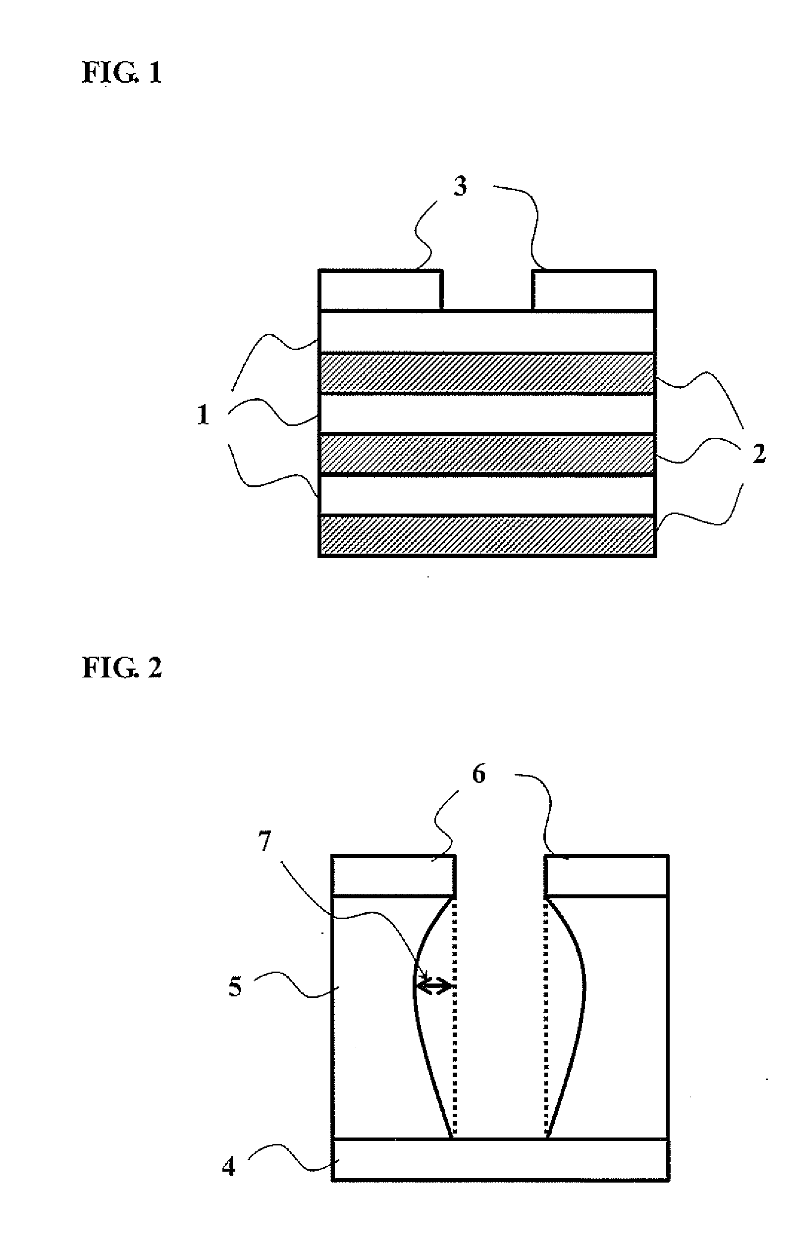
a technology of dry etching and etching plate, which is applied in the manufacturing of semiconductor/solid-state devices, basic electric elements, electrical equipment, etc., can solve the problems of bumps and depressions on the side wall (inner surface) of the through hole, or the diameter decrease in the lower, so as to suppress the unevenness of the hole diameter and reduce the bumps and depressions

Active Publication Date: 2016-07-28
CENT GLASS CO LTD
View PDF2 Cites 30 Cited by
  • Summary
  • Abstract
  • Description
  • Claims
  • Application Information

AI Technical Summary

Benefits of technology

[0021]The dry etching method of the present invention enables equal-rate etching of p-Si and SiOx. In the case where this dry etching method is used to form a through hole in a laminated film in which a plurality of p-Si layers and SiOx layers are alternate...

Problems solved by technology

Thus, the etching process of Non-Patent Document 2 is time-consuming and presents the problem that the time for formation of the through hole in the p-Si/SiOx laminated film increases with increase in the number of the p-Si and SiOx layers in the laminated film (i.e. the time for production of the memory cells increases with the number of lamination of the memory cells).
The etching process of Non-Patent Document 2 also presents the problem of bumps and depressions on a side wall (inner surface) of the through hole, or dec...

Method used


Image

  • Dry Etching Method
  • Dry Etching Method
  • Dry Etching Method

Examples


example 1

Etching Operation

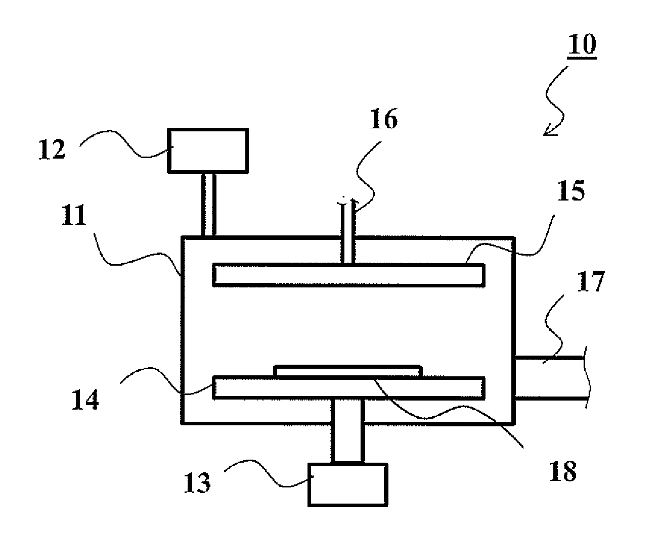
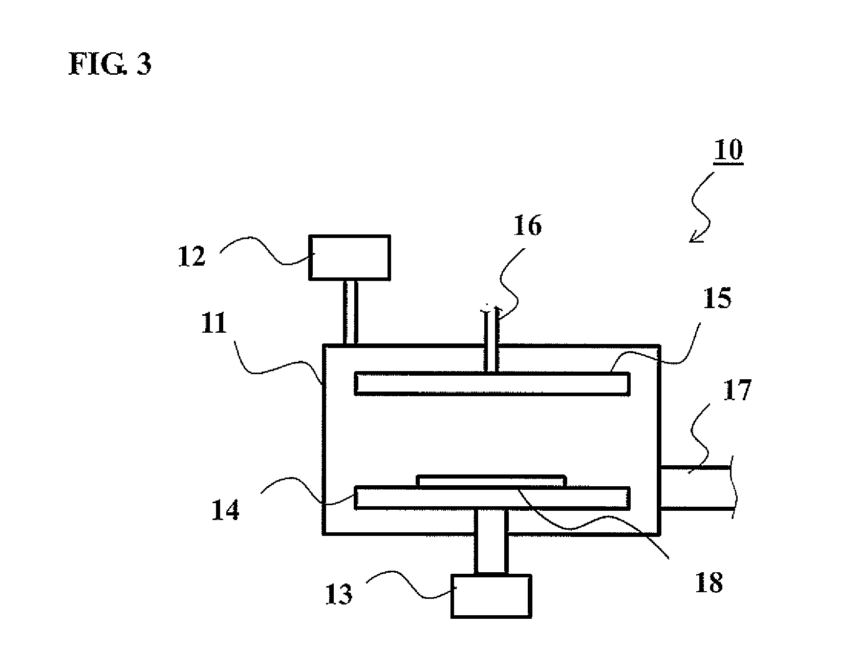
[0053]The dry etching agent was prepared by mixing 10 vol % of C3HF5 (HFO-1225zc) as a fluorocarbon, 1 vol % of IF7 as an additive gas and 89 vol % of Ar as an inert gas. In the etching operation, the dry etching gas was fed at 100 sccm to the chamber 11; and the pressure inside the chamber 11 was set to 1 Pa. The test sample 18 was subjected to etching by generating a plasma gas from the dry etching agent with the supply of 400 W of high-frequency power. The density of the high-frequency power supplied was 1.0 W / cm2; and the bias voltage applied was 500V. As the respective gas components are substantially the same in molar volume (volume per 1 mol), the volume ratio of the gas components can be read as the mol ratio.

[0054]Performance Evaluation 1: Etching Rate Ratio

[0055]An etching rate ratio was evaluated by the following procedure to examine whether or not p-Si and SiOx were etched at equal rates.

[0056]The etching rate of p-Si was determined based on a difference...

example 2

[0061]The etching operation was performed under the same conditions as in Example 1, except that the dry etching agent used contained 10 vol % of C3HF5 (HFO-1225zc) as the fluorocarbon, 2 vol % of IF7 as the additive gas and 88 vol % of Ar as the inert gas. The etching performance was the evaluated in the same manner as in Example 1.

example 3

[0062]The etching operation was performed under the same conditions as in Example 1, except that the dry etching agent used contained 10 vol % of C3H2F4 (HFO-1234ze(E)) as the fluorocarbon, 2 vol % of IF7 as the additive gas and 88 vol % of Ar as the inert gas. The etching performance was the evaluated in the same manner as in Example 1.


PUM


Abstract

Disclosed is a dry etching method for a laminated film in which at least one silicon layer and at least one silicon oxide layer are laminated together. The dry etching method includes generating a plasma gas from a dry etching agent and etching the laminated film with the plasma gas under the application of a bias voltage. The dry etching agent contains an unsaturated hydrofluorocarbon represented by the following formula: C3HxFy where x is an integer of 1 to 5; y is an integer of 1 to 5; and x and y satisfy a relationship of x+y=4 or 6, and iodine heptafluoride. The volume of the iodine heptafluoride in the dry etching agent is 0.1 to 1.0 times the volume of the unsaturated hydrofluorocarbon in the dry etching agent.

Description

FIELD OF THE INVENTION[0001]The present invention relates to a dry etching method using an unsaturated hydrofluorocarbon-containing dry etching agent.BACKGROUND OF THE INVENTION[0002]In the field of semiconductor manufacturing, fine processing is nowadays close to physical limits. As a solution to overcome such physical limits, it has been proposed to realize high integration of semiconductor devices, in particular NAND flash memories, by stacking device components in height directions. The research and development of three-dimensional NAND flash memories etc. are being actively pursued using the proposed high-integration techniques.[0003]One such type of three-dimensional NAND flash memory is disclosed in e.g. Toshiba Review, Vol. 66, No. 9, pages 16-19 (2011) (hereinafter referred to as “Non-Patent Document 1”). For manufacturing of this three-dimensional NAND flash memory, a laminated film is first formed as a charge holding part by alternately laminating a plurality of layers 1 ...

Claims


Application Information

Patent Timeline
IPC IPC(8): H01L21/311H01L21/02
CPCH01L21/02164H01L21/31116H01L21/32137
Inventor OOMORI, HIROYUKIKIKUCHI, AKIOU
Owner CENT GLASS CO LTD
Why Eureka
Try Eureka