Vacuum microwave drying apparatus

a drying apparatus and microwave technology, applied in drying machines, lighting and heating apparatus, furnaces, etc., can solve the problems of long drying cycle, large power consumption, steam drying method, etc., and achieve the effect of improving the utilization ratio of microwave, temperature gradient, and reducing the moisture content of dried materials

Inactive Publication Date: 2010-01-07
LI SHENG
View PDF7 Cites 19 Cited by
  • Summary
  • Abstract
  • Description
  • Claims
  • Application Information

AI Technical Summary

Benefits of technology

[0034]Because the material transferring mechanism is arranged to multilayer in the same one tank, the above vacuum microwave drier provided by the present invention can take full advantage of device space and improve utilization ratio of microwave; In addition, because the continuous feeding mechanism, the continuous discharging mechanism and the material transferring me

Problems solved by technology

The steam drying method has defects such as long drying cycle, large power consumption, low efficiency, non-homogeneous heating, poor performance of preserving freshness, and so on.
Though the microwave drying method can increase the rate of material drying, but owing to the higher drying temperature, the drying quality and performance of the material is prone to be affected.
This technical solution has the following defects: the transmission and discharging of the material is discontinuous dur

Method used


Image

  • Vacuum microwave drying apparatus
  • Vacuum microwave drying apparatus
  • Vacuum microwave drying apparatus

Examples


first embodiment

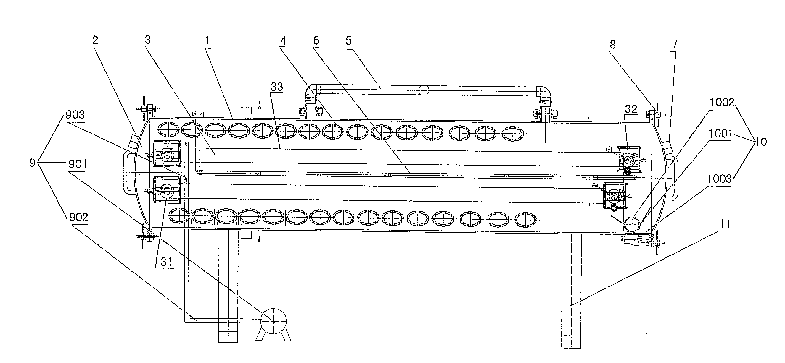
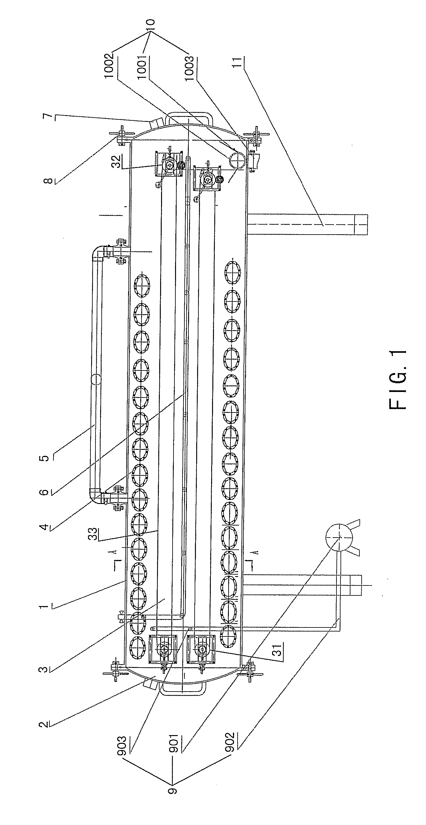
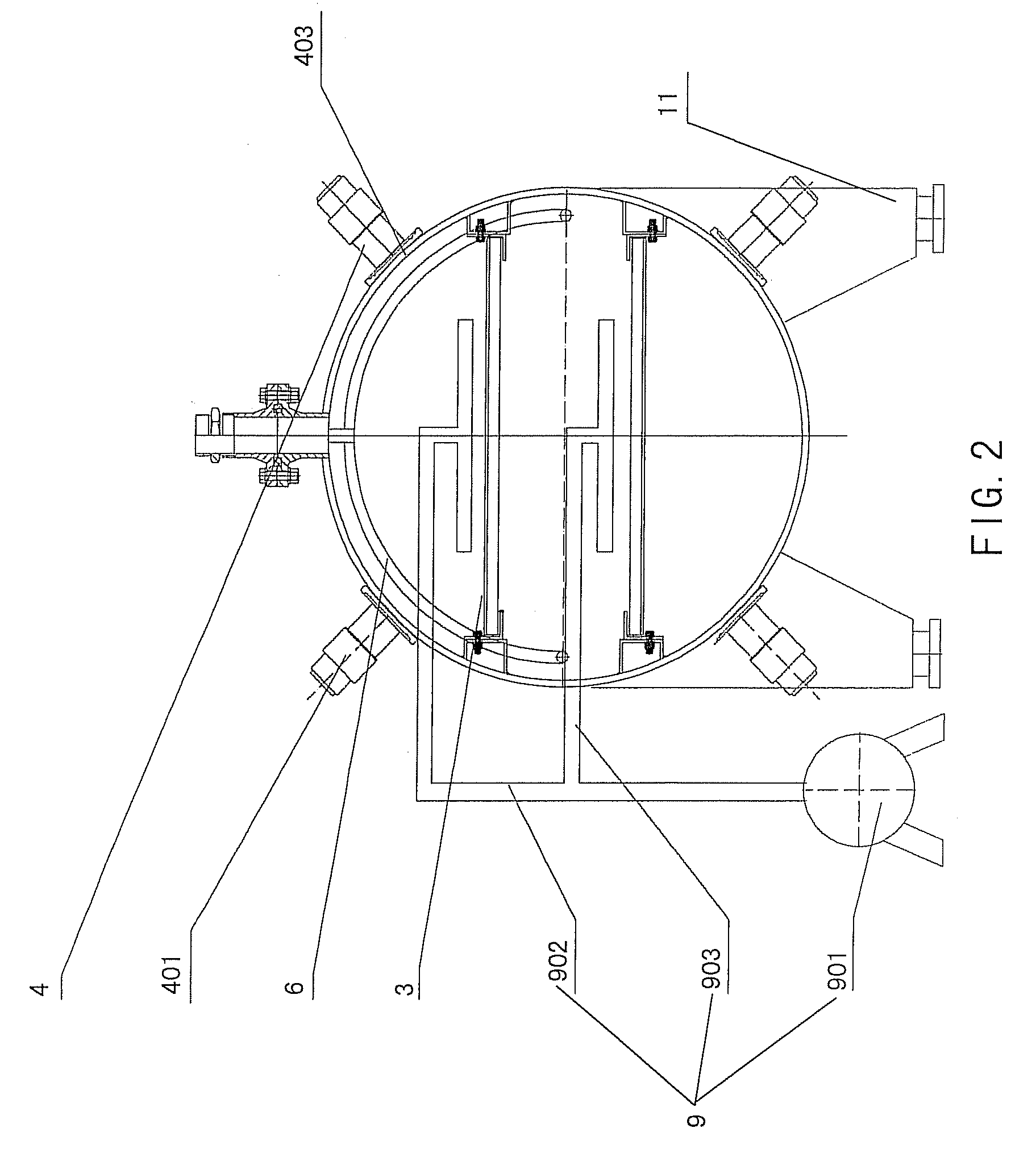
[0085]FIG. 1 is a schematic view showing a structure of a vacuum microwave drying apparatus according to the present invention, and FIG. 2 is a sectional view cut along A-A line of FIG. 1.

[0086]As shown in FIG. 1 and FIG. 2, the vacuum microwave drying apparatus provided by the present invention mainly consists of a tank 1, tank closures 2, a vacuum system, a continuous feeding mechanism 9, a continuous discharging mechanism 10, at least two layers of material transferring mechanism 3 as well as a plurality of microwave heating means 4.

[0087]The tank 1 may has a cylinder shape as a whole, but the whole shape of the tank 1 is not limited to this, it may be any shape which can realize the objectives of the present invention. The tank 1 and tank closures 2 located at two ends of the tank 1 jointly define a containing space for containing the material transferring mechanisms 3. The tank 1 and the tank closures 2 may be made of a metal material to prevent the microwave for drying materia...

second embodiment

[0098]FIG. 3 is a schematic view showing a structure of a vacuum microwave drying apparatus according to the present invention. FIG. 4 is a sectional view cut along line B-B of FIG. 3.

[0099]As shown in FIG. 3 and FIG. 4, the mainly structure difference between the second embodiment and first embodiment of the vacuum microwave drying apparatus of the present invention lies in that, the vacuum microwave drying apparatus of the present invention is provided with 4 layers of material transferring mechanism 3, and the microwave feed-in openings 403 of the microwave heating means 4 are arranged above each layer of the material transferring mechanism 3.

[0100]The microwave heating means 4 are disposed into a plurality of lines that are parallel to the material transferring mechanisms 3, and each line of microwave heating means 4 is corresponded to the position of each material transferring mechanism 3 one to one.

[0101]The microwave generators 401 of the microwave heating means 4 are arrange...

third embodiment

[0105]FIG. 7 is a schematic view showing a structure of a vacuum microwave drying apparatus according to the present invention, in which a containing space in a tank is divided into a drying chamber and a cooling chamber by a separator. FIG. 8 is a sectional view cut along line D-D of FIG. 7.

[0106]As shown in FIG. 7 and FIG. 8, beside the structure provided by the first embodiment and second embodiment, the third embodiment further comprises a separator 12, a microwave suppressor 13 and a cooling unit.

[0107]The separator 12 divides the containing space in the tank 1 into a drying chamber disposed on the left hand in FIG. 7 (in other words, on the side of the feeding pipe 902) and a cooling chamber disposed on the right hand side in FIG. 7 (in other words, on the side of the material catching pot 1001). The separator 12 is made of a material which can obstruct the microwave from transmission, such as metal, to stop the microwave in the drying chamber and prevent the leakage of the mi...


PUM


Abstract

A vacuum microwave drying apparatus, includes: a tank (1); a tank enclosure (2), which defines an accommodate space with the tank; a vacuum system, which is communicated with the accommodate space through a vacuum pipe (5); a continuous feed-in mechanism (9), including a feed-in pipe (902) communicated with the accommodate space, the continuous feed-in mechanism (9) sending materials into the accommodate space through the feed-in pipe (902) continuously; a continuous feed-out mechanism (10), which sends the materials out of the accommodate space continuously; at least two layers of material sending mechanisms (3), each of which is arranged in the accommodate space in parallel along the longitudinal direction of the tank, to send the materials from the continuous feed-in mechanism (9) into the continuous feed-out mechanism (10); and a plurality of microwave heating devices (4), each of which has a microwave feed-in port (403), which is located in the accommodate space, to send microwave to the accommodate space, the microwave being used to dry the materials which is sent by the material sending mechanism (3). The vacuum microwave drying apparatus can reduce the occupied space, and can perform a continuous drying operation.

Description

BACKGROUND OF THE INVENTION[0001]1. Field of the Invention[0002]The present invention relates to a material drying and sterilizing equipment utilized in a field such as pharmacy, foodstuff, chemical engineering, paper-making, particularly, relates to a vacuum microwave drying equipment.[0003]2. Description of Related Art[0004]In many fields, such as pharmacy, foodstuff chemical engineering, paper-making and so on, a material drying process is usually related.[0005]A conventional material drying method includes the steam drying method and the microwave drying method, etc. The steam drying method has defects such as long drying cycle, large power consumption, low efficiency, non-homogeneous heating, poor performance of preserving freshness, and so on. Though the microwave drying method can increase the rate of material drying, but owing to the higher drying temperature, the drying quality and performance of the material is prone to be affected.[0006]The microwave vacuum drying method ...

Claims


Application Information

Patent Timeline
IPC IPC(8): F26B3/347
CPCF26B5/041F26B17/04F26B5/048
Inventor LI, SHENG
Owner LI SHENG
Why Eureka
Try Eureka