Exhaust emission control device

a technology of exhaust gas and control device, which is applied in the direction of electrical control, exhaust treatment electric control, separation process, etc., can solve the problem of insufficient removal of no/sub>x/sub>in the exhaust gas

Active Publication Date: 2010-01-07
HINO MOTORS LTD
View PDF2 Cites 35 Cited by
  • Summary
  • Abstract
  • Description
  • Claims
  • Application Information

AI Technical Summary

Benefits of technology

[0022](III) When the ammonia reducing catalyst for oxidization treatment of the surplus ammonia is arranged just behind the selective reduction catalyst, the surplus ammonia having passed through the se

Problems solved by technology

However, in a field of automobile where safety is hard to assure as to running with ammonia itself being loaded, researches have been made nowadays on use of nontoxic urea water as reducing agent.
For e

Method used


Image

  • Exhaust emission control device
  • Exhaust emission control device
  • Exhaust emission control device

Examples


Embodiment Construction

[0040]An embodiment of the invention will be described in conjunction with the drawings.

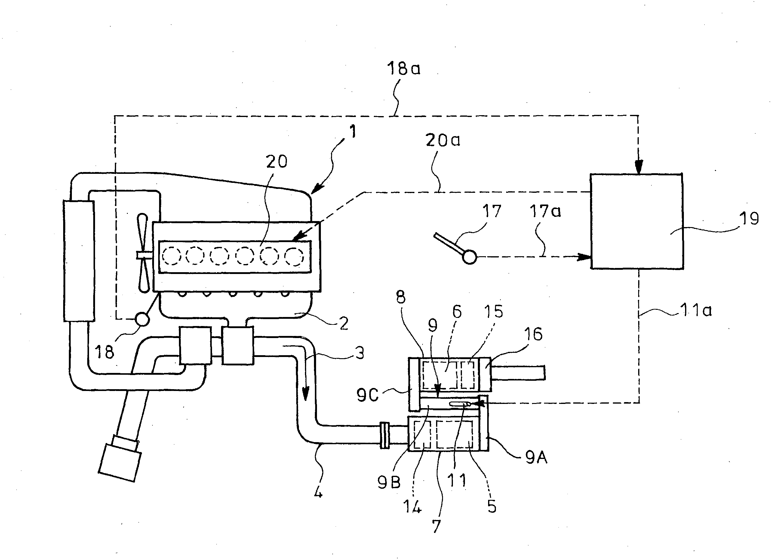
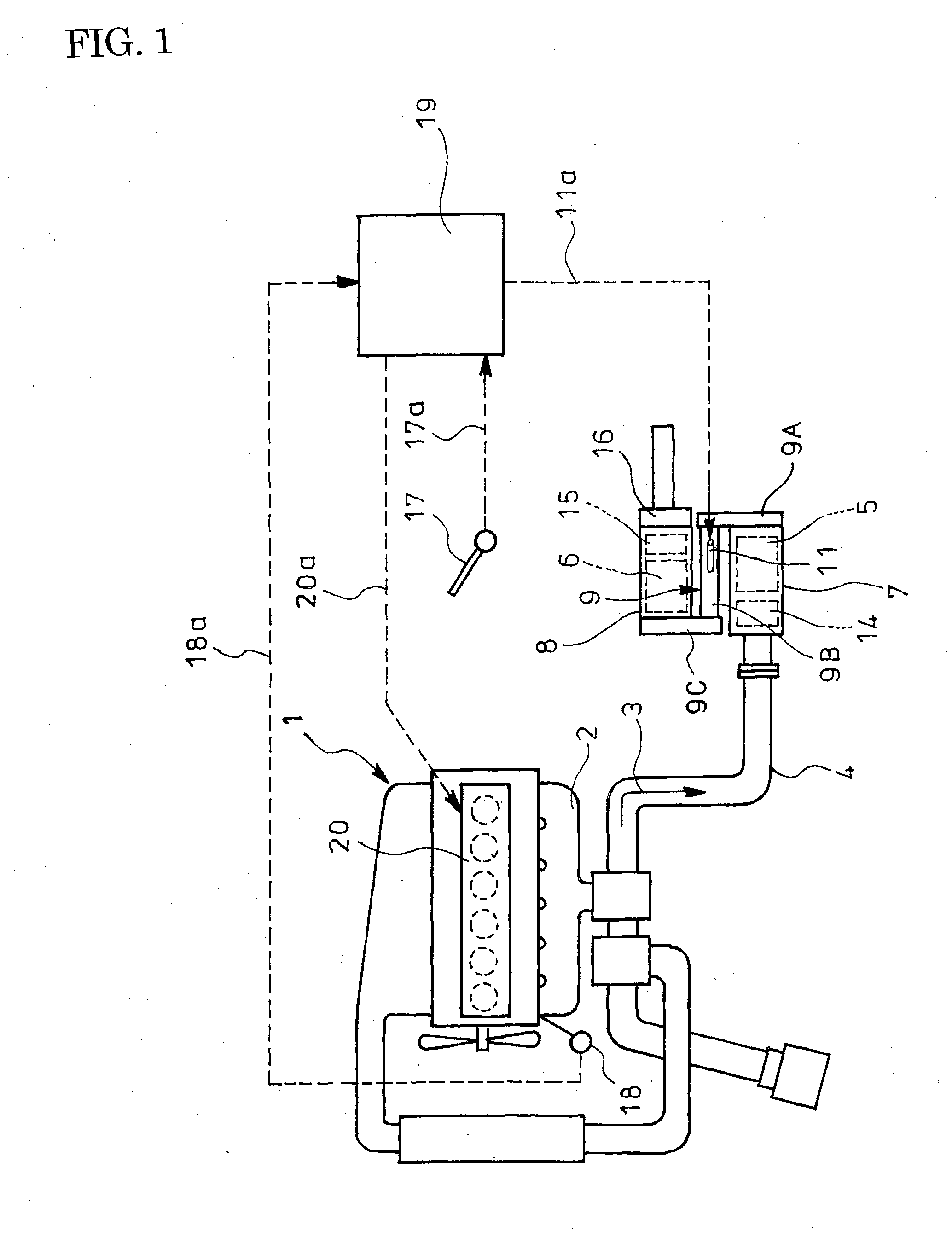
[0041]FIG. 1 shows the embodiment of the invention. In the embodiment of the exhaust emission control device, incorporated in an exhaust pipe 4 through which exhaust gas 3 flows from a diesel engine 1 via an exhaust manifold 2 is a particulate filter 5 housed in a casing 7 to capture particulates in the exhaust gas 3; arranged downstream of and in parallel with the particulate filter 5 and housed in a casing 8 is selective reduction catalyst 6 having a property capable of selectively reacting NOx with ammonia even in the presence of oxygen. A rear end of the particulate filter 5 is connected to an front end of the selective reduction catalyst 6 through an S-shaped communication passage 9 such that the exhaust gas 3 discharged through the rear end of the particulate filter 5 is passed via forward turnabout into the front end of the neighboring selective reduction catalyst 6.

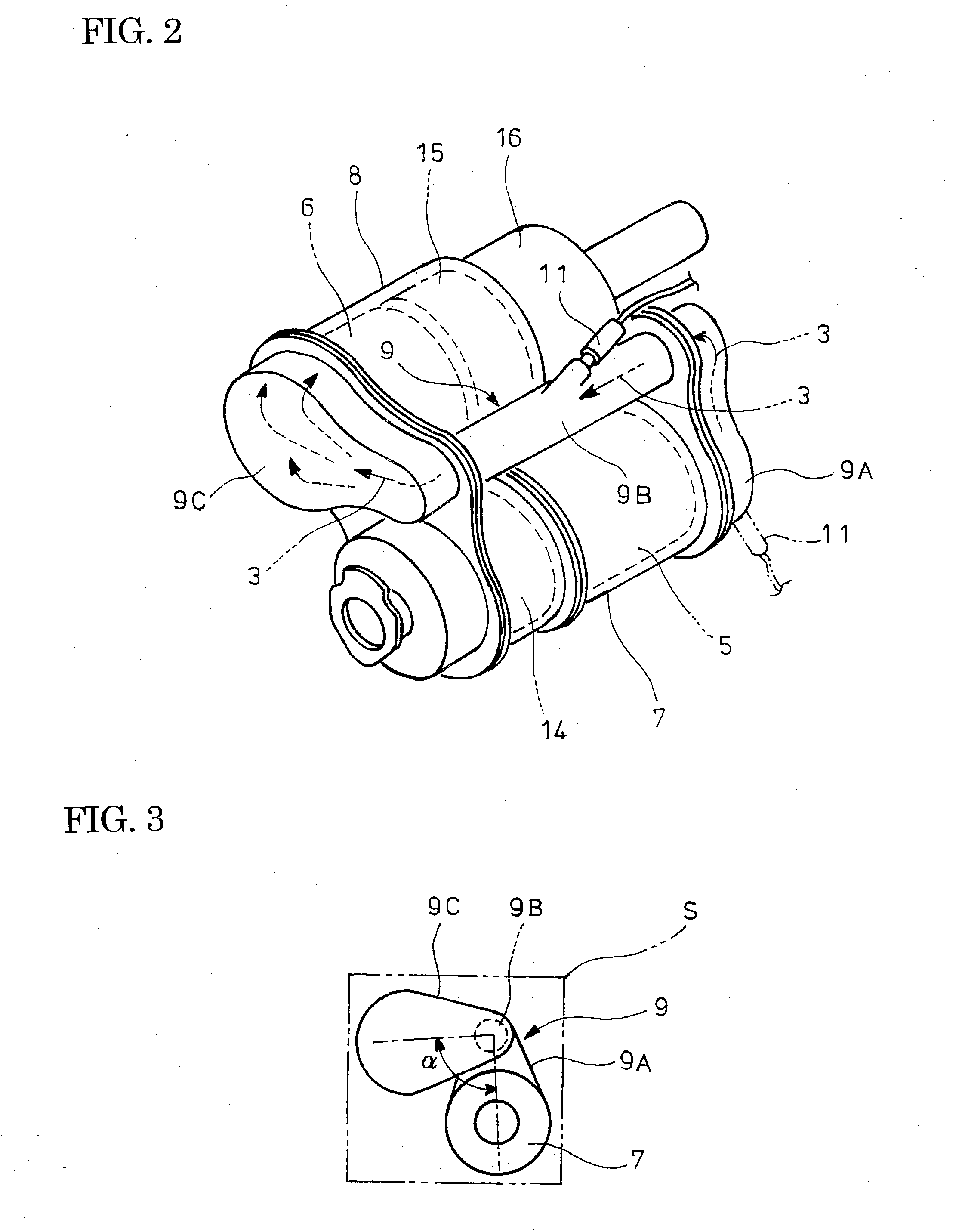
[0042]As shown in FIG. ...


PUM


Abstract

The object of the invention is to improve mountability on a vehicle by realizing a compact arrangement of a particulate filter 5 and selective reduction catalyst 6 while ensuring satisfactory reaction time for generation of ammonia from urea water. In an exhaust emission control device having particulate filter 5 incorporated in an exhaust pipe 4, selective reduction catalyst 6 capable of selectively reacting NOx with ammonia under the presence of oxygen being arranged downstream of the particulate filter, urea water as reducing agent being adapted to be added between the selective reduction catalyst 6 and the particulate filter 5, the particulate filter 5 is arranged in parallel with the selective reduction catalyst 6. An S-shaped communication passage 9 is arranged for introduction of the exhaust gas 3 from a rear end of the particulate filter 5 to a front end of the adjacent selective reduction catalyst 6 in a forward folded manner. A urea water addition injector 11 is arranged midway of the communication passage 9.

Description

TECHNICAL FIELD [0001]The present invention relates to an exhaust emission control device.BACKGROUND ART [0002]Conventionally, some diesel engines have selective reduction catalyst incorporated in an exhaust pipe through which exhaust gas flow, said catalyst having a feature of selectively reacting NOx with a reducing agent even in the presence of oxygen. A required amount of reducing agent is added upstream of the reduction catalyst and is reacted on the catalyst with NOx (nitrogen oxides) in the exhaust gas to thereby reduce a concentration of the discharged NOx.[0003]Meanwhile, effectiveness of ammonia (NH3) used as a reducing agent for reduction and purification of NOx is well known in a field of industrial flue gas denitration, for example, in a plant. However, in a field of automobile where safety is hard to assure as to running with ammonia itself being loaded, researches have been made nowadays on use of nontoxic urea water as reducing agent.[0004]More specifically, when the...

Claims


Application Information

Patent Timeline
IPC IPC(8): F01N9/00F01N3/035
CPCB01D46/0027B01D46/0061B01D46/42B01D2279/30F01N3/035F01N3/106F01N13/011F01N3/2892F01N2610/02F02D41/029Y02T10/24F01N13/009F01N3/2066Y02A50/20Y02T10/12B01D46/82
Inventor KOWADA, MINORU
Owner HINO MOTORS LTD
Why Eureka
Try Eureka