Apparatus and method for cooling an exhaust gas

a technology of exhaust gas and apparatus, which is applied in the direction of mechanical apparatus, engine components, machines/engines, etc., can solve the problem of filter obstruction

Active Publication Date: 2010-01-07
GM GLOBAL TECH OPERATIONS LLC
View PDF11 Cites 32 Cited by
  • Summary
  • Abstract
  • Description
  • Claims
  • Application Information

AI Technical Summary

Benefits of technology

[0009]In another embodiment, a method for cooling an exhaust gas of an exhaust treatment device of an engine is provided. The method comprising: directing an exhaust gas through a first fluid conduit having a variable nozzle defined by at least two dissimilar materials adjacent to each other and extending from the first fluid conduit. The variable nozzle is received in an inlet end of a second fluid conduit and the variable nozzle is disposed in the second fluid conduit proximate to the inlet end of the second fluid conduit such that a fluid inlet opening is defined between an outer periphery of the variable nozzle and an inner surface of the inl...

Problems solved by technology

Continued particulate buildup in the diesel particulate filter is undesirable t...

Method used


Image

  • Apparatus and method for cooling an exhaust gas
  • Apparatus and method for cooling an exhaust gas
  • Apparatus and method for cooling an exhaust gas

Examples


Embodiment Construction

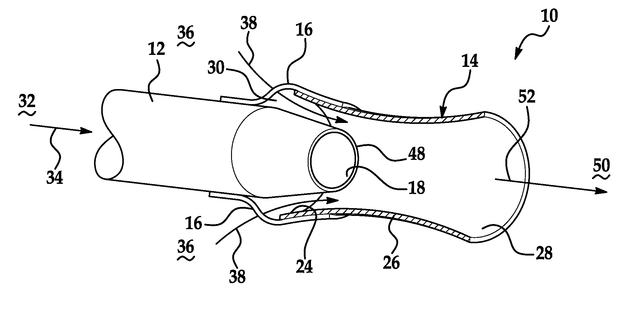
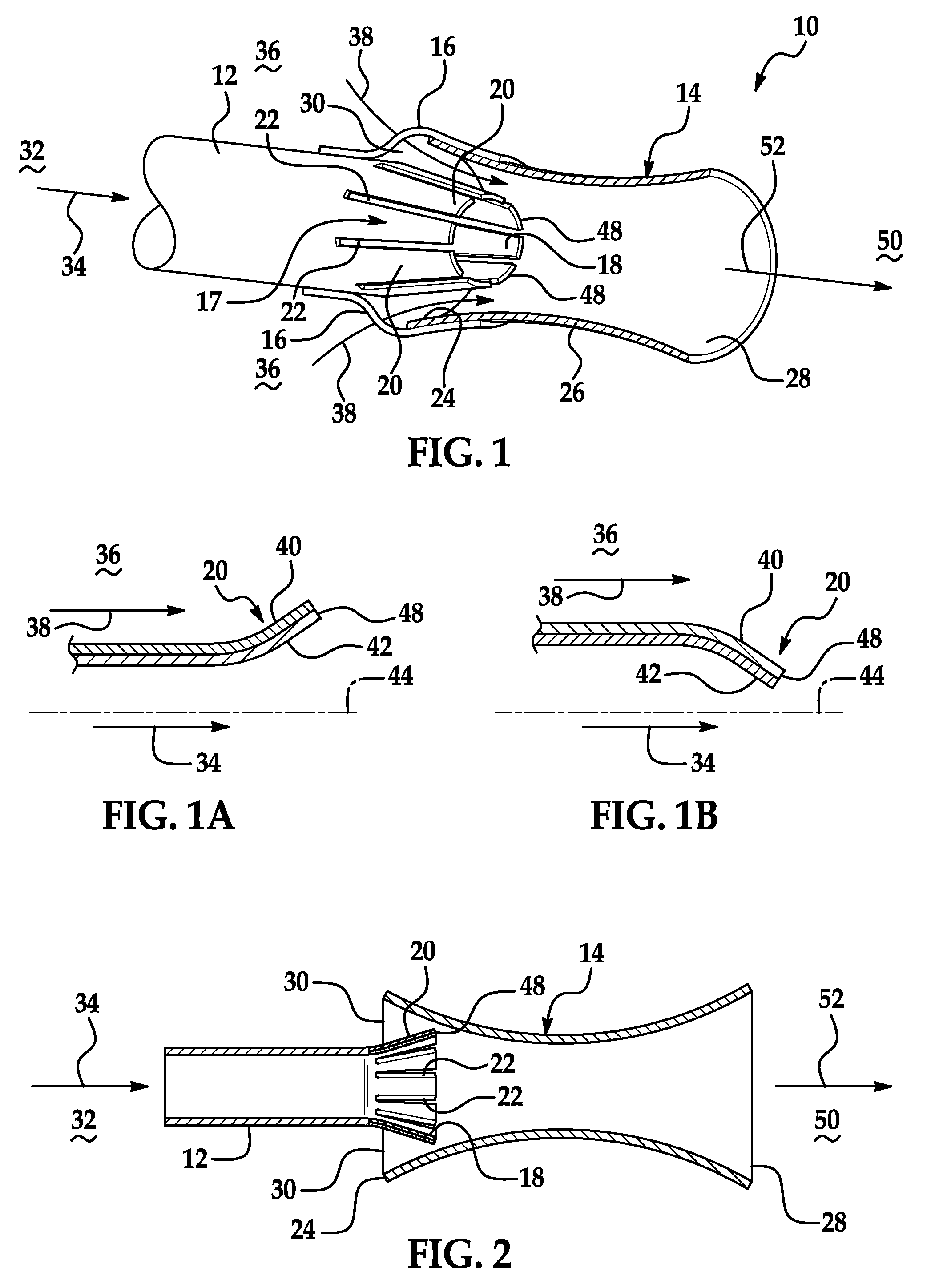
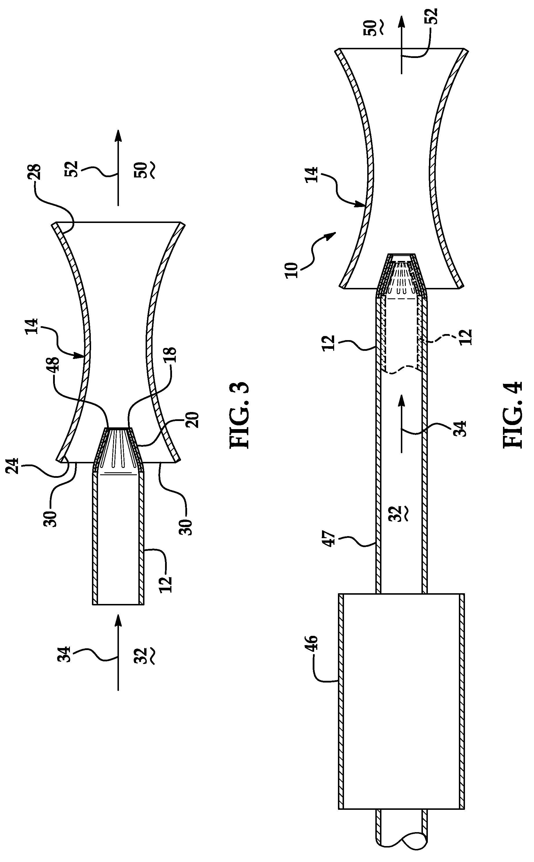
[0022]Referring now to FIGS. 1-4, and in accordance with one non-limiting embodiment, an exhaust gas cooling apparatus 10 is illustrated. The exhaust gas cooling apparatus has a first fluid conduit 12 and a second fluid conduit 14. Although, the first and second fluid conduits are illustrated as having circular configurations and openings any cross-sectional shape for the first and second fluid flow conduits is contemplated as long as the desired results are achieved. Non-limiting examples of such configurations include oval, ellipse, square, rectangular and equivalents thereof.

[0023]The first fluid conduit is secured to the second fluid conduit by a plurality of securement members or stand offs 16. The stand offs are configured such that fluid can flow into the second fluid conduit from areas surrounding the first fluid conduit. The first fluid conduit is configured to receive an exhaust gas from an engine (not shown) and has a variable nozzle 17 with an opening 18 positioned to di...


PUM


Abstract

An exhaust gas cooling apparatus and method for cooling an exhaust gas is provided. The exhaust cooling apparatus has a first fluid conduit and a variable nozzle extending from the first fluid conduit. The variable nozzle being disposed in an inlet end of a second fluid conduit, wherein the variable nozzle has at least two dissimilar materials adjacent to each other and a fluid inlet opening is located between an outer periphery of the variable nozzle and an inner surface of the inlet end of the second fluid conduit. The at least two dissimilar materials vary the size of an opening of the variable nozzle by moving toward or away from a center line of the first fluid conduit in response to a temperature of an exhaust gas flowing through the first fluid conduit.

Description

CROSS REFERENCE TO RELATED APPLICATION[0001]This application claims the benefit of U.S. Patent Application Ser. No. 61 / 077,362, filed Jul. 1, 2008, the contents of which are incorporated herein by reference thereto.FIELD OF THE INVENTION[0002]Exemplary embodiments of the present invention are related to a fluid entrainment apparatus and, more specifically, to a fluid entrainment apparatus to cool an exhaust gas.BACKGROUND[0003]Manufacturers of vehicles that employ internal combustion engines, more particularly diesel engines, are striving to reduce and control exhaust emissions and comply with current and future emission standards for the release of oxides of nitrogen (NOx), unburned and partially oxidized hydrocarbons (HC), carbon monoxide (CO), particulate matter, and other emissions, (i.e., hydrogen sulfide (H2S) and ammonia (NH3)). In order to reduce the previously mentioned emissions, diesel engines are typically operated with exhaust gas after-treatment systems.[0004]Exhaust g...

Claims


Application Information

Patent Timeline
IPC IPC(8): F01N3/02
CPCF01N3/05F01N13/082F01N2260/14Y02T10/20F01N2270/10F01N2470/30F01N2530/00F01N2270/02Y02T10/12
Inventor FREESE, V, CHARLES E.
Owner GM GLOBAL TECH OPERATIONS LLC
Why Eureka
Try Eureka