Wind-driven turbine cells and arrays

a technology of wind-driven turbines and arrays, which is applied in the direction of motors, solar thermal energy generation, sustainable buildings, etc., can solve the problems of imbalance, no action, and noise and vibration produced by a large turbine, and achieves low noise and vibration, easy integration, and fast response to wind speed changes.

Inactive Publication Date: 2010-01-07
GRUMAZESCU MIHAI
View PDF16 Cites 21 Cited by
  • Summary
  • Abstract
  • Description
  • Claims
  • Application Information

AI Technical Summary

Benefits of technology

[0075]Nature taught us so many times that power is in numbers. So the idea of creating a wind cell small, light and cheap enough to be the basic structure of wind panels and arrays that can be easily integrated as architectural elements for covering the exterior walls of buildings is coming from that direction. The wind cell has two key advantages: having a small and light rotor, responds very fast to wind speed changes converting it in electric energy at a very low level of sound and vibration. In this case, the integration of wind changes is done at electrical level as all wind cells in a panel are charging a battery. As a bonus, this concept has a side-effect with major implications in the design of building structures: it reduces significantly the wind pressure on the windward wall itself. In the back of any wind turbine, the wind speed is much lower than in front of it but no wind turbine was mounted against a wall to use this effect.
[0076]The invention therefo

Problems solved by technology

The main drawback of the prior art is the level of noise and vibration produced by a large turbine.
However, any imbalance shows up once per revolution and there is nothing you can do about it.
Other disadvantages are related to how bad a roof mounted turbine looks or the cost of designing and raising a building structure for the integrated turbines.
Kelly does not teach mounting the array on the exterior wall of the building and also does not teach ducted shrouding to concentrate moving air against a particular part of each turbin

Method used


Image

  • Wind-driven turbine cells and arrays
  • Wind-driven turbine cells and arrays
  • Wind-driven turbine cells and arrays

Examples


Embodiment Construction

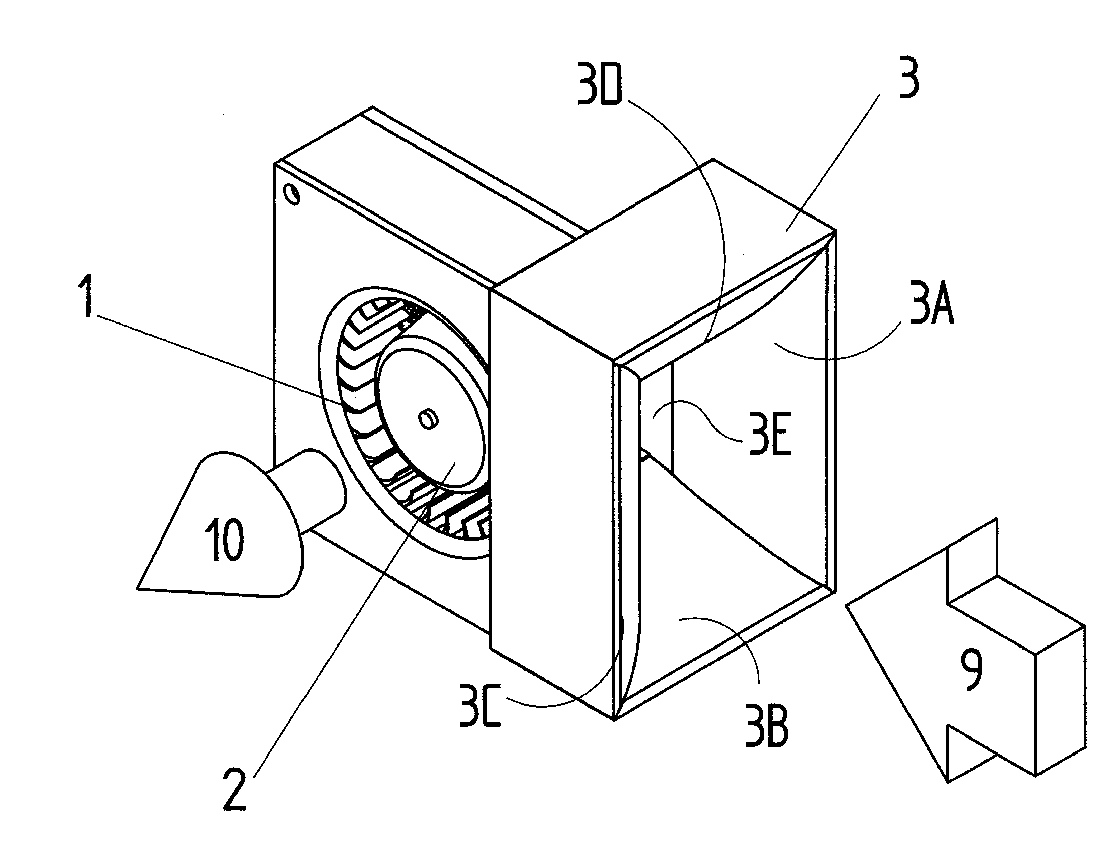
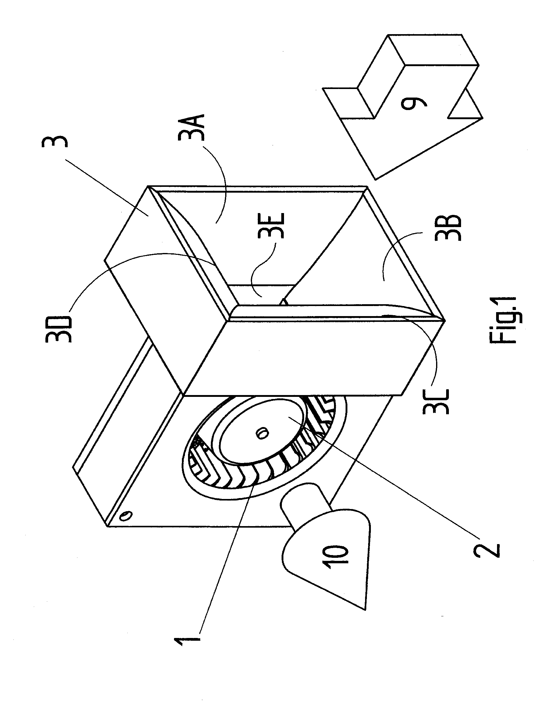
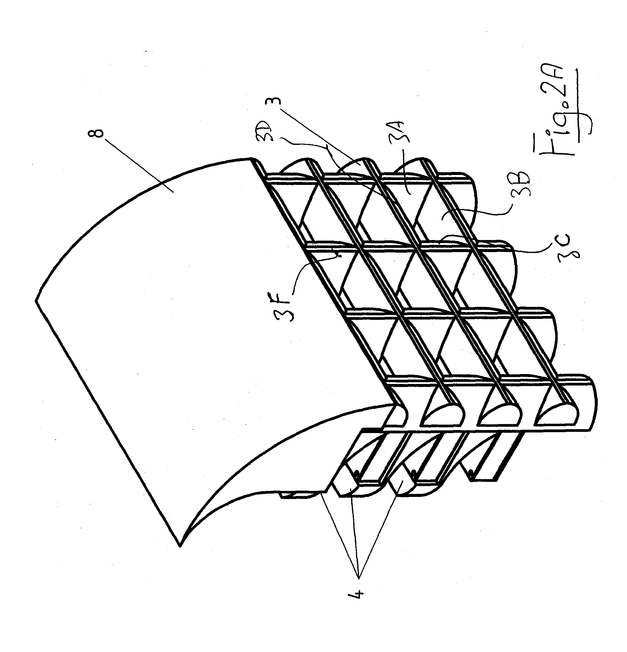
[0105]A preferred embodiment of a wind cell according to the invention is shown in FIG. 1. A centrifugal micro turbine 1 drives an electrical generator 2 when wind blows through a shroud 3. From the airflow point of view, the centrifugal turbine has a tangential input 9 and an axial output of residual air 10. That is, the turbine has a series of angularly spaced blades arranged in a cylindrical pattern around the axis of rotation of the turbine with an open area inside an inside edge of the blades. Each blade extends parallel to the axis and is inclined so that air impinging on the blade is directed from the blade radially inwardly into the interior of the turbine into the open area while applying a force to the blades to cause rotation of the turbine. As conventionally, the blades are curved so that the air is smoothly turned from the initial point of impact on a generally tangential line inwardly toward the open inner area while applying the turning force on the blades and thus on...


PUM


Abstract

An electrical energy generating system is mounted on a structure and includes a ducted shroud facing the wind and concentrating its flow through Coanda effect to inlet mouths each directed to a respective one of a plurality of small centrifugal or axial turbines connected to brushless DC generators. The air exits each turbine axially and is directed to flow along the wall, merging with the natural vertical airflow and is discarded at the top of the structure where another deflector creates a negative pressure helping the residual airflow to merge with wind blowing over the top. The efficiency of generation is proportional to the difference between the front wind pressure and the back air pressure. While each wind cell generates only a few tens of watts, the array can generate a large amount of electricity to be used for the structure and/or to be made available to a grid.

Description

[0001]This invention relates to an apparatus for generating electrical energy from wind and to the mounting of such an apparatus on a suitable structure such as a building, an upstanding fixed structure such as a billboard, oil and gas platforms, cliffs or chimneys and on movable structures such as ship deck structures and airships.BACKGROUND OF THE INVENTION[0002]This invention relates mainly to the urban wind power field in which there are two known approaches. The first is the concept of roof mounted wind turbines, either vertical or horizontal axis, and the second is that of horizontal axis turbines fully integrated into the building fabric. The roof mounted turbines can be from large to micro diameters and have the advantage of being self wind-oriented while the integrated turbines are only very large and with a fixed position which is compensated by shaping the building like a boomerang that accelerates airflow over the turbine.[0003]The main drawback of the prior art is the l...

Claims


Application Information

Patent Timeline
IPC IPC(8): F03D9/00F03D1/02
CPCF03D1/02F03D1/04F03D3/002F03D3/0409F05B2220/7062Y02E10/74F05B2240/40F05B2240/911Y02B10/30Y02E10/465Y02E10/728F05B2240/13Y02E10/46Y02E10/72F03D9/25F03D9/34
Inventor GRUMAZESCU, MIHAI
Owner GRUMAZESCU MIHAI
Why Eureka
Try Eureka