Solenoid valve for brake system

Active Publication Date: 2010-01-07
HL MANDO CORP
View PDF6 Cites 2 Cited by
  • Summary
  • Abstract
  • Description
  • Claims
  • Application Information

AI Technical Summary

Benefits of technology

[0017]Therefore, it is an aspect of the present invention to provide a solenoid valve for a brake system

Problems solved by technology

This may cause the braking pressure to be partially transmitted to a master cylinder through an inlet.
Therefore, inserting the magnet core into the bore may require an excessively long length and complex configuration of the magnet core, resul

Method used


Image

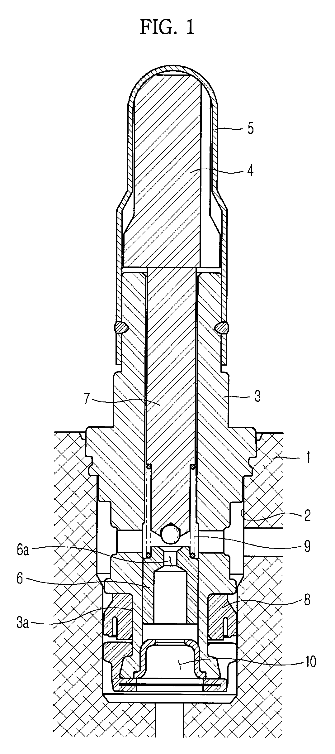
  • Solenoid valve for brake system
  • Solenoid valve for brake system
  • Solenoid valve for brake system

Examples


Embodiment Construction

[0028]Reference will now be made in detail to the embodiment of the present invention, examples of which are illustrated in the accompanying drawings, wherein like reference numerals refer to like elements throughout.

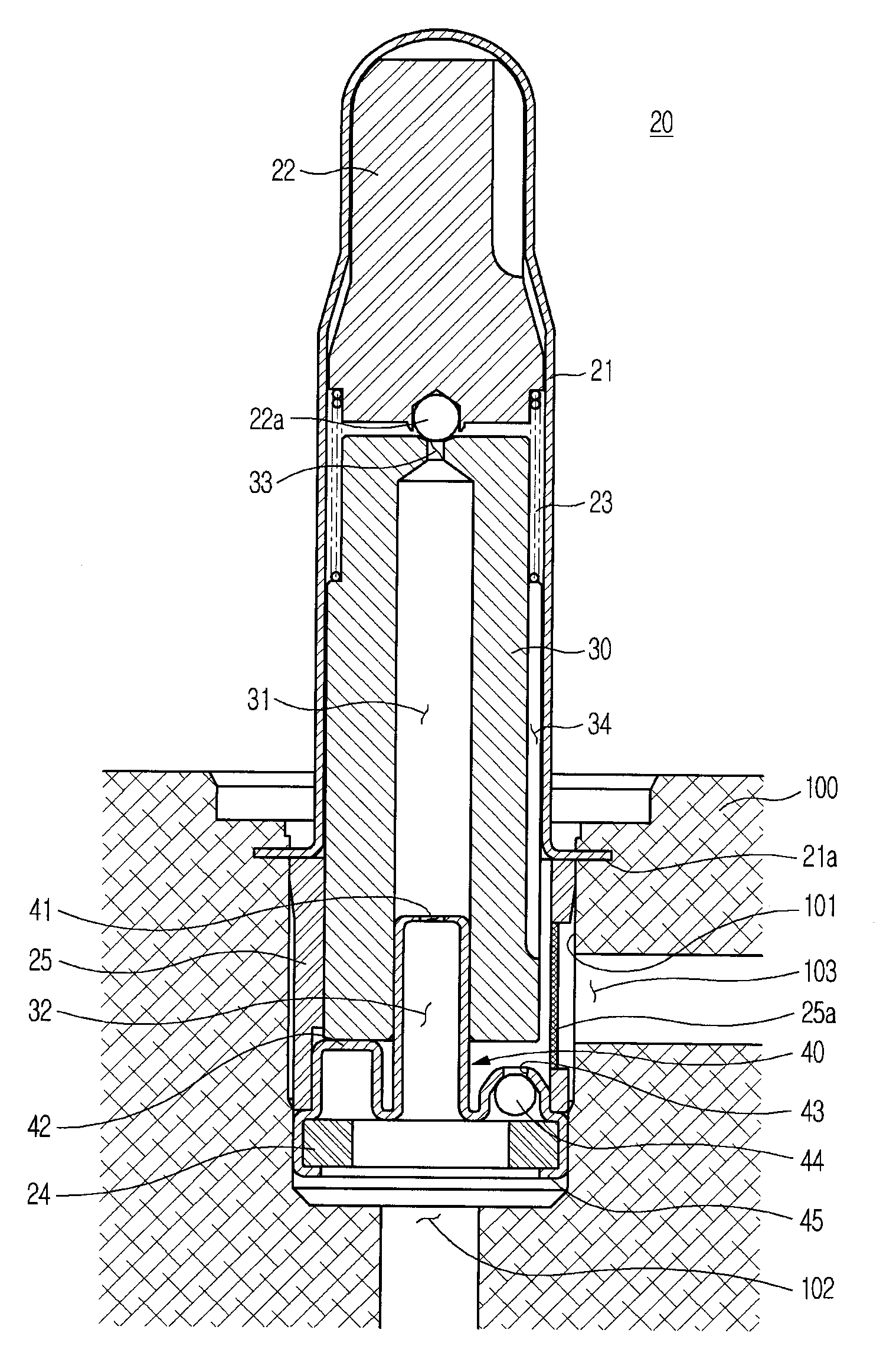
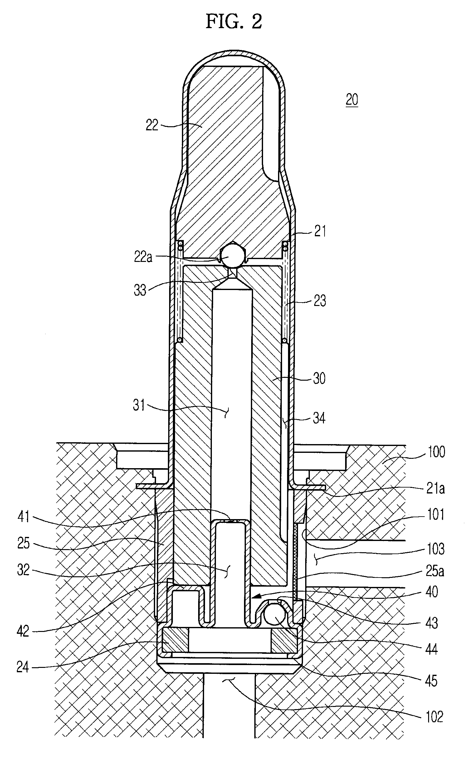
[0029]Referring to FIG. 2, a valve 20 for a brake system according to the present embodiment is installed in a bore 101 formed in a modulator block 100 in the form of a hexahedral block. An inlet 102 is provided below the bore 101 and is connected to a master cylinder (not shown) to receive oil from the master cylinder. Also, an outlet 103 is provided at a side of the bore 101 and is connected to a brake (not shown) to transmit the oil to the brake.

[0030]In the present embodiment, the shown valve 20 is a normally opened type solenoid valve and thus, is normally kept in an opened state but closes a flow-path upon receiving power.

[0031]The valve 20 includes a cylindrical sleeve 21 having an inner hollow, an armature 22 movably received in the sleeve 21, a magnet core 30 r...


PUM


Abstract

Disclosed herein is a solenoid valve for a brake system to reduce manufacturing costs via a shorter length and more simplified configuration of a magnet core. In the solenoid valve for a brake system to be mounted in a bore of a modulator block having an inlet and an outlet, the solenoid valve includes a magnet core having a center longitudinal penetrating hole and an entrance and exit for oil flow, an armature movably provided at one end of the magnet core and serving to open or close the exit, a valve seat provided at the other end of the magnet core, and a sleeve in which the armature and magnet core are received, the sleeve being fixed to the bore.

Description

CROSS-REFERENCE TO RELATED APPLICATION[0001]This application claims the benefit of Korean Patent Application No. 2008-0063778, filed on Jul. 2, 2008 in the Korean Intellectual Property Office, the disclosure of which is incorporated herein by reference.BACKGROUND[0002]1. Field[0003]Embodiments of the present invention relate to a solenoid valve for a brake system to assure easier manufacture and lower manufacturing costs than the related art.[0004]2. Description of the Related Art[0005]A general vehicular anti-lock brake system is designed to prevent wheel lockup when braking hard by controlling braking pressure applied to wheels based on sensed tire slip.[0006]This assures directional stability and steering control of wheels without tire slip during braking and consequently, safe braking.[0007]This type of brake system includes a plurality of solenoid valves that opens or closes flow-paths of brake hydraulic lines to control braking pressure. Solenoid valves may be classified into ...

Claims


Application Information

Patent Timeline
IPC IPC(8): B60T8/36
CPCB60T8/363F16K27/10B60T17/04B60T8/36B60T8/00
Inventor LEE, CHUNG JAE
Owner HL MANDO CORP
Why Eureka
Try Eureka