Unitary light guide plate, light guide plate unit, planar lighting device and liquid crystal display device

a technology of light guide plate and light guide plate, which is applied in the direction of lighting and heating apparatus, instruments, mechanical instruments, etc., can solve the problems of difficult to achieve the irregular light amount of a backlight unit having a thickness of 10 mm or less, and achieve the effect of improving light emission efficiency, reducing cost, and reducing the thickness of the backlight uni

Active Publication Date: 2010-01-07
FUJIFILM CORP
View PDF9 Cites 69 Cited by
  • Summary
  • Abstract
  • Description
  • Claims
  • Application Information

AI Technical Summary

Benefits of technology

[0067]According to the first and second embodiments of the first aspect of the present invention, the light guide plate is thin and lightweight, emission efficiency of light from the light exit plane with respect to light emitted from the light source can be increased, and a size of the light exit plane of the light guide plate can be set larger.
[0068]According to the third embodiment of the first aspect of the present invention, by using the unitary light guide plate of the first embodiment and the light guide plate unit of the second embodiment, the thin and lightweight planar lighting device can be manufactured at a lower cost, which enables an increase in emission efficiency of light emitted from the light exit plane with respect to light emitted from the light source, and setting of an illumination surface to a la

Problems solved by technology

The backlight unit is expected to become thinner in the future, but it is thought that, in the direct type, the real

Method used


Image

  • Unitary light guide plate, light guide plate unit, planar lighting device and liquid crystal display device
  • Unitary light guide plate, light guide plate unit, planar lighting device and liquid crystal display device
  • Unitary light guide plate, light guide plate unit, planar lighting device and liquid crystal display device

Examples


third embodiment

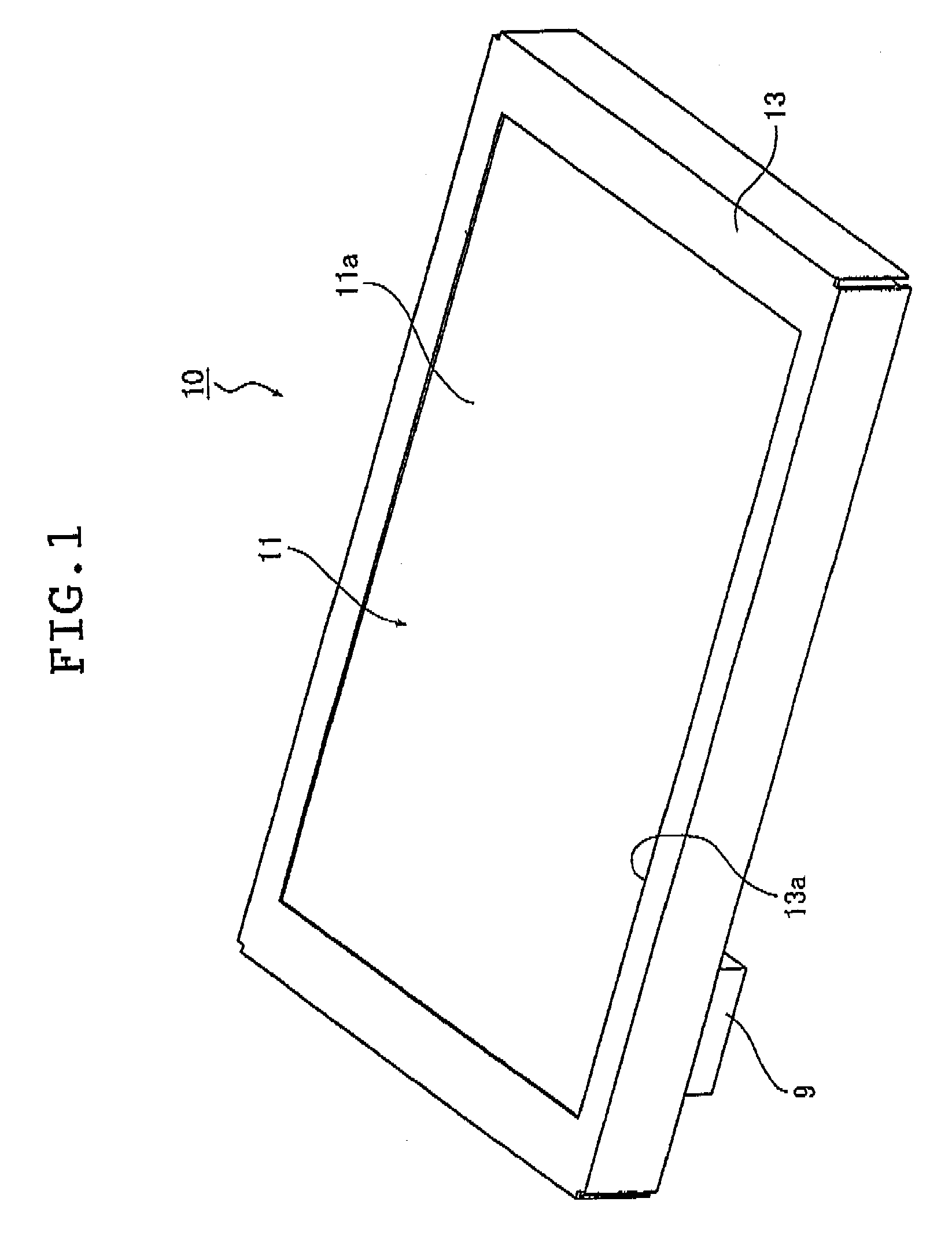
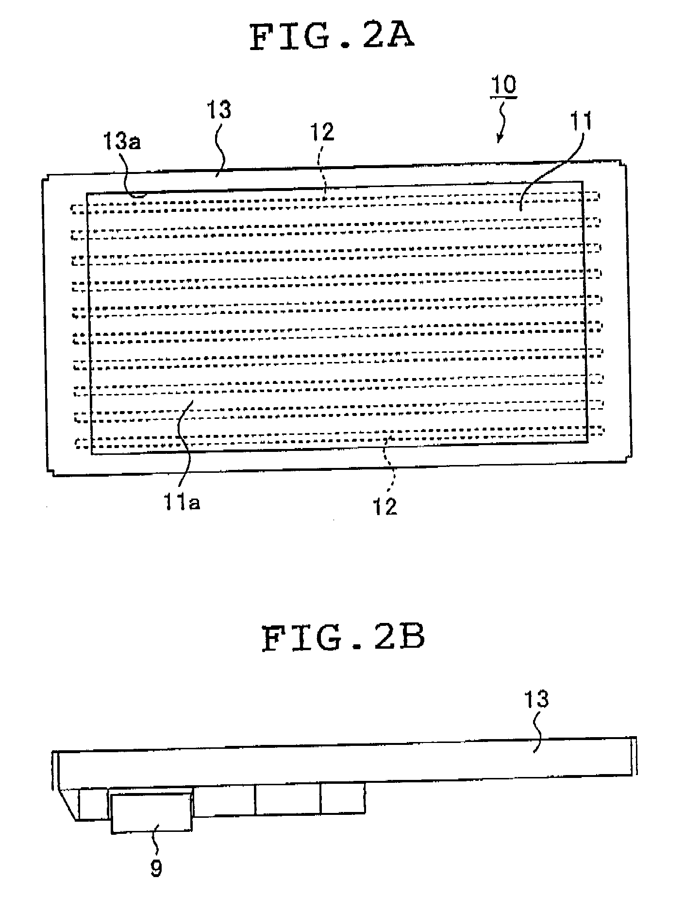
[0165]FIG. 1 is a schematic perspective view illustrating the exterior of the planar lighting device according to the present invention, which is a first aspect of the present invention, seen from a light exit plane side. FIGS. 2A, 2B, 2C and 2D are each a front view, a bottom view, a lateral view, and a rear view of the planar lighting device illustrated in FIG. 1. In the following drawings including these drawings, the planar lighting device is illustrated under magnification in a thickness direction thereof for ease of understanding.

[0166]As illustrated in FIG. 1 and FIGS. 2A to 2D, a planar lighting device 10 includes a lighting device main body 11 including a plurality of linear light sources 12 and emitting uniform light from a rectangular light exit plane 11a, a housing 13 accommodating the lighting device main body 11 therein and including a rectangular opening 13a on a side of the light exit plane 11a (surface side), an inverter accommodating portion 9 provided on a side of...

first embodiment

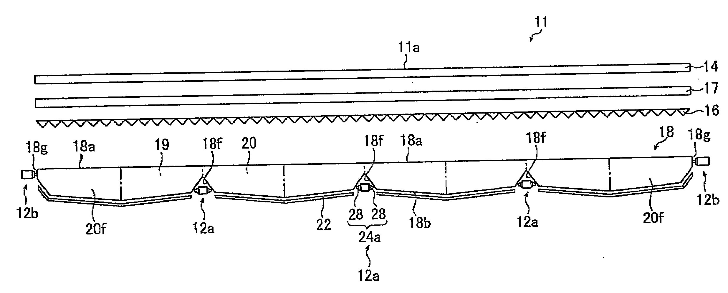
[0168]The lighting device main body 11 is for emitting uniform light from a rectangular light exit plane 11a, and basically configured, as illustrated in FIG. 3, so as to form a rectangular light exit plane 18a on the light exit plane 11a side by coupling a plurality of linear light sources 12 and a plurality of unitary light guide plates 19 or 20 of the first aspect of the present invention in parallel, and includes a light guide plate unit 18 having a plurality of parallel grooves 18f formed on the backside of the light exit plane 18a to accommodate the linear light sources 12, two prism sheets 16 and 17 arranged on the light exit plane 18a side of the light guide plate unit 18, and a diffusion sheet 14.

second embodiment

[0169]Note that, as illustrated in FIG. 3, the lighting device main body 11 is constituted of the light guide plate unit 18 of the first aspect of the present invention, and needless to say, the two prism sheets 16 and 17 and the diffusion sheet 14 arranged over the light guide plate unit 18 all have sizes (areas) substantially equal to that of the light exit plane 18a of the light guide plate unit 18.

[0170]The coupling of the unitary light guide plates 19 and 20 of the first embodiment of the first aspect of the present invention constituting the light guide plate unit 18 described above, and the coupling of the unitary light guide plates 19 or 20 for constituting the light guide plate unit 18 are described below in detail.

[0171]In FIG. 3, the linear light source 12 includes linear light sources 12a disposed in the parallel grooves 18f formed in the light guide plate unit 18 for emitting light from both sides toward the opposing wall planes of the parallel groove 18f, and linear li...


PUM


Abstract

A unitary light guide plate includes a light exit plane, a thick portion located substantially on a center portion of the light exit plane, thin end portions formed on both sides of the thick portion, a half portion of a parallel groove formed on a backside of the light exit plane to accommodate linearly arranged light sources, inclined back portions arranged so as to become thinner from the thick portion to the thin end portions, and scattering means for scattering light entering from the light sources accommodated in the parallel groove into the thin end portions and propagated through the inclined back portions toward the thick portion. A light guide plate unit has two or more of the unitary light guide plates coupled together in such a way that respective light exit planes are arranged to form a same plane.

Description

TECHNICAL FIELD[0001]The present invention relates to a unitary light guide plate which serves as a transparent light guide plate for diffusing light from a linear light source or a linearly arranged point-like light source in a plane direction to emit a more uniform illumination light from a light exit plane, a light guide plate unit, a planar lighting device using this, a unitary light guide plate for converting incident light from a point-like light source into planar outgoing light, and a planar lighting device and a liquid crystal display device using this.BACKGROUND ART[0002]Conventionally, for a liquid crystal display device, a backlight unit that emits light from a backside of a liquid crystal panel (LCD) to illuminate the liquid crystal panel has been used. The backlight unit is normally configured by using a light source for illumination, a light guide plate for diffusing light emitted from this light source to irradiate the liquid crystal panel with the light, and compone...

Claims


Application Information

Patent Timeline
IPC IPC(8): G02F1/13357F21V8/00
CPCG02B6/0021G02B6/0048G02B6/0068G02B6/0055G02B6/0061G02B6/0053
Inventor KURAMITSU, MASAYUKIENDO, TOSHIAKI
Owner FUJIFILM CORP
Why Eureka
Try Eureka