Communication System and Communication Apparatus

a communication system and communication technology, applied in the field of communication system and communication apparatus, can solve the problems of packets being discarded, user does not recognize the path failure, and the communication system is inferior to the synchronous communication network, so as to reduce the loss of packets

Inactive Publication Date: 2010-01-07
HITACHI LTD
View PDF2 Cites 43 Cited by
  • Summary
  • Abstract
  • Description
  • Claims
  • Application Information

AI Technical Summary

Benefits of technology

[0061]According to the present invention, the communication time periods of a working system and a protection system in a packet communication network can be arbitrated in order to decrease a packet loss at path switching in a packet relaying network. Moreover, according to the invention, the adjustments of communication time periods can be occasionally performed when they have changed due to a failure or the like on a packet communication network.

Problems solved by technology

At the present stage, it is said that the packet communication network can freely alter a network configuration owing to the autonomous operations of devices, whereas it is inferior to the synchronous communication network in point of the stability of the path.
Besides, if the vocal data can complete switching in a short time (for example, about 50 ms), a user does not recognize the path failure.
In a case where any communication failure has occurred in the path being used, the path temporarily becomes a nonexistent situation during a time period required for the control packet analysis and the path switching process, with the result that some packets might be discarded.

Method used


Image

  • Communication System and Communication Apparatus
  • Communication System and Communication Apparatus
  • Communication System and Communication Apparatus

Examples


embodiment 1

3. Operation of Embodiment 1

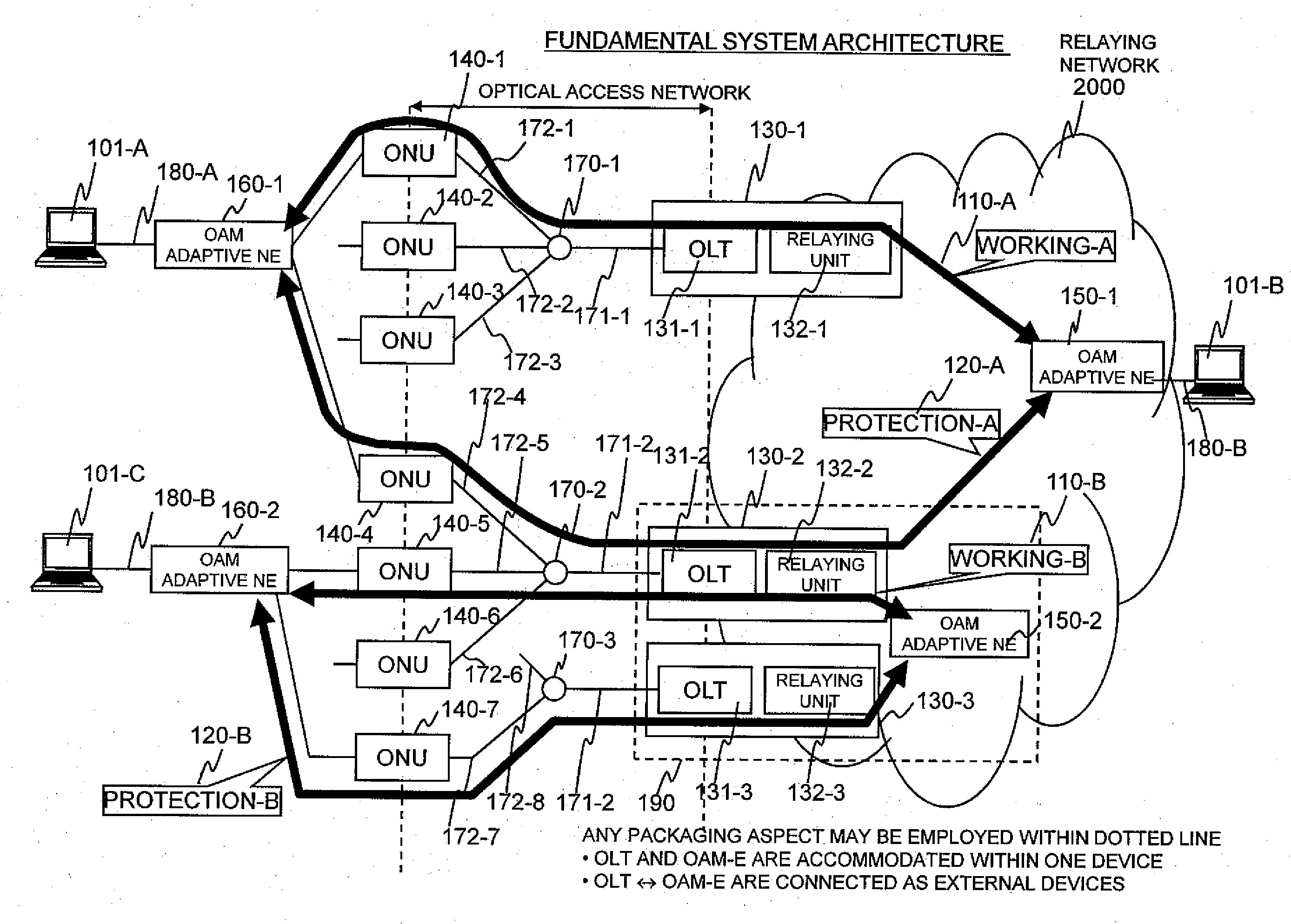
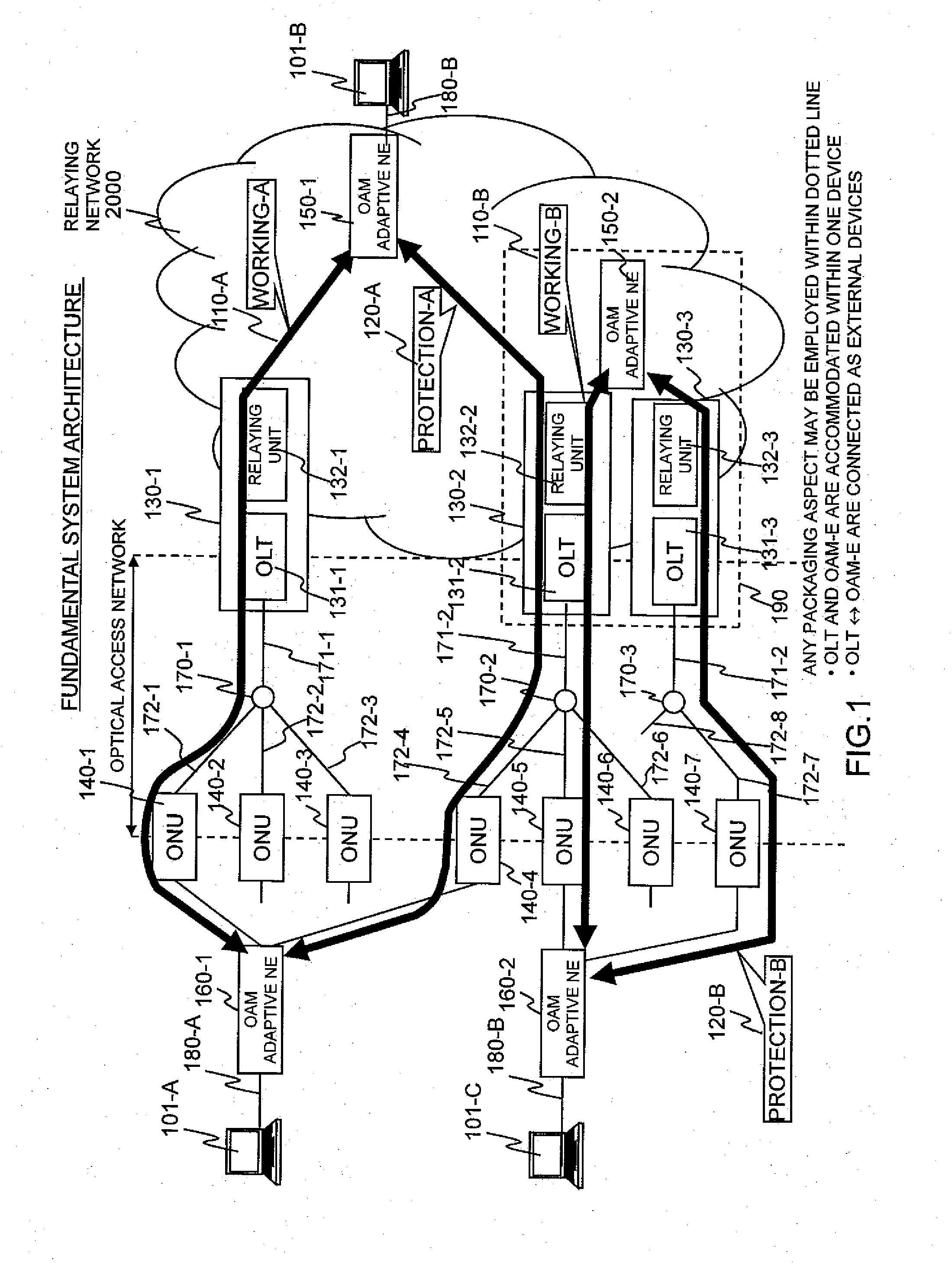
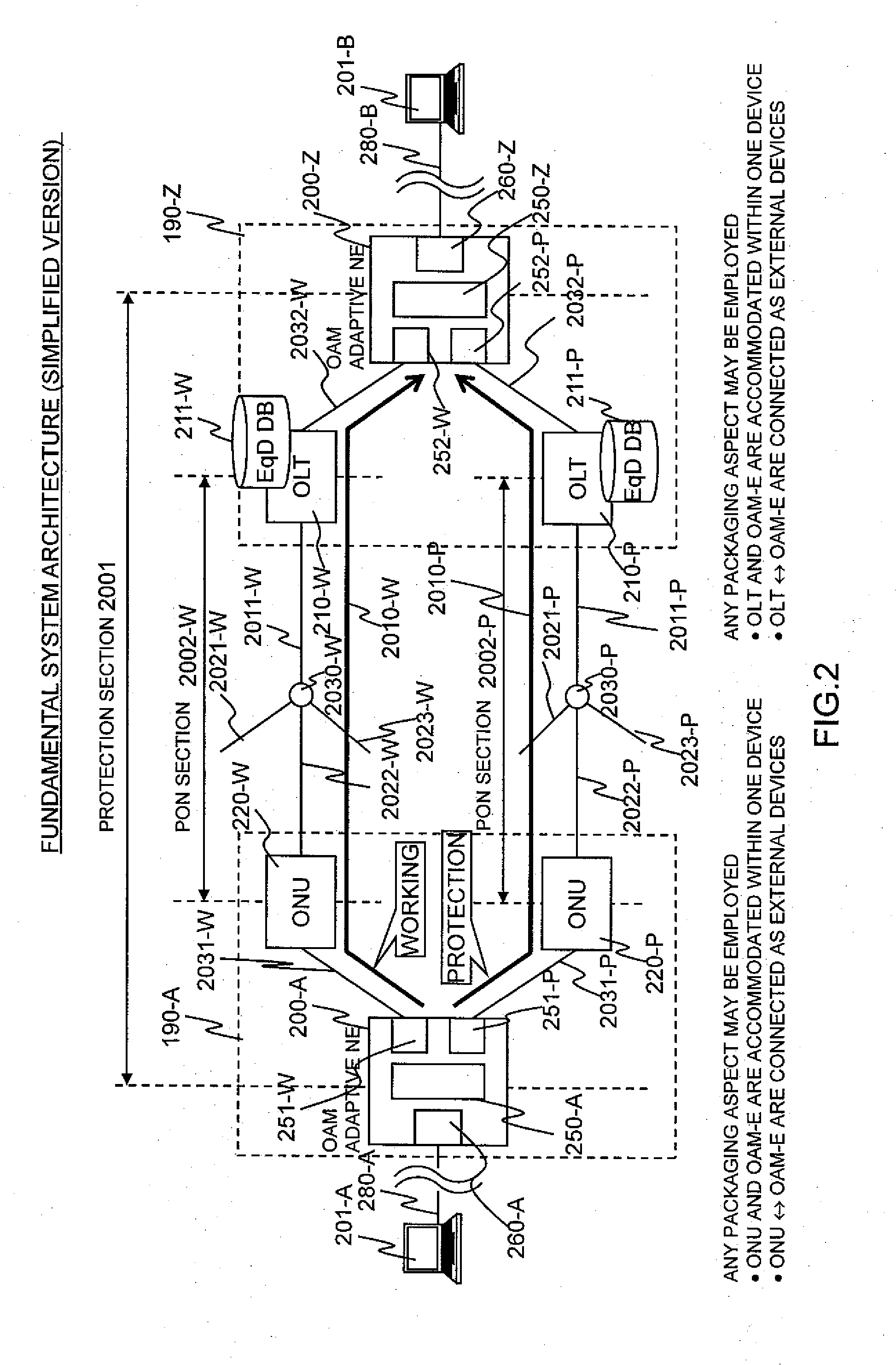
[0106]In order to incarnate Embodiment 1, the OAM adaptive NEs 200-A and 200-Z include delay DBs 300-A and 300-Z (refer to a delay DB 1292 in FIG. 7 to be stated later), respectively.

[0107]In Embodiment 1, the difference between the communication time periods of the working path 2010-W and the protection path 2010-P is measured, and it is fed back to the OLTs 210. In order to measure the difference between the communication time periods of both the paths, measuring frames are sent from the transmission side OAM adaptive NE 200-A or 200-Z of the protection section 2001, respectively and simultaneously to both the paths, and the arrival times of reception frames are compared in the reception side OAM adaptive NE 200-Z or 200-A, so as to grasp the difference of the communication time periods.

[0108]Operations in the case of measuring the communication time periods in the direction (uplink direction) from the OAM adaptive NE 200-A to the OAM adaptive NE 200-Z,...


PUM


Abstract

Communication time period measuring frames are simultaneously sent from an OAM adaptive device on a transmission side, to both a working path and a protection path. In an OAM adaptive device on a reception side, reception times of the frames having arrived from both the paths are checked so as to measure a time period difference between both the paths. The time period difference is fed back to a logic distance adjustment function of each PON section to determine required communication time periods of the PON sections respectively included in a working system and a protection system. Communication time periods of the working system and the protection system in a packet communication network are arbitrated in order to decrease a packet loss at line switching in a packet relaying network.

Description

CLAIM OF PRIORITY[0001]The present application claims priority from Japanese patent application JP 2008-175828 filed on Jul. 4, 2008, the content of which is hereby incorporated by reference into this application.BACKGROUND OF THE INVENTION[0002]1. Field of the Invention[0003]The present invention relates to a communication system and a communication apparatus, and more particularly to a communication system and a communication apparatus for adjusting or arbitrating the communication time periods of a working communication path and a protection communication path.[0004]2. Description of the Related Art[0005]In general, with increase in a demand for a broad band, the introduction of a large-capacity access line employing an optical fiber has advanced as a user-oriented access line, instead of communication technology which is based on a telephone line such as digital subscriber line (DSL). At present, a passive optical network (PON) system in which the optical fiber can be shared by ...

Claims


Application Information

Patent Timeline
Patent Type & Authority Applications(United States)
IPC IPC(8): H04L12/26H04J3/16H04L12/44H04L45/247H04L45/586H04L47/56
CPCH04J3/0682H04L12/5695H04L43/0852H04L45/22H04L45/26H04Q2011/0081H04L47/746H04L47/762H04L47/826H04Q11/0062H04Q2011/0079H04L45/62H04L47/70
Inventor MIZUTANI, MASAHIKOYAJIMA, YUSUKEKANNO, TAKAYUKIYASUDA, TAKESHI
Owner HITACHI LTD
Why Eureka
Try Eureka