Detection and reduction of ringing artifacts based on block-grid position and object edge location

a technology of object edge location and block grid position, applied in the field of processing data, can solve problems such as gibb's phenomenon artefacts and noise, and types of coding artefacts

Inactive Publication Date: 2010-01-07
PACE PLC
View PDF2 Cites 20 Cited by
  • Summary
  • Abstract
  • Description
  • Claims
  • Application Information

AI Technical Summary

Benefits of technology

[0038]In its basic idea the present invention is directed to the observation that ringing is spatially localized within blocks, which contain an object edge or a part thereof. Consequently such blocks containing an object edge pixel are defined as affected pixel blocks above. In particular this is true for a strong object edge. The invention has recognized clearly that if a e.g. DCT block includes at least one pixel from an object edge, then ringing may impact all pixels within this block, but at the same time, adjacent and / or neighboring blocks, which do not contain an object edge, i.e. the mentioned object edge or another object edge, will be free from ringing. In other words, blocks being free of pixels of an object edge will be basically free from ringing and won't cause ringing in neighboring or adjacent blocks. Consequently such blocks not containing an object edge pixel are defined as not-affected pixel blocks above. This new insight is supplemented by the perception, that the artefact becomes visible only if a spatial activity of a ringing area, i.e. one or more blocks, is higher than the activity of background. If the background contains a texture, then ringing is masked by spatial high frequencies of that texture. This new insight leads to an advantageous innovative concept for the detection of regions of a picture which are potentially affected by artefacts due to imperfect transform coding.
[0040]Contrary to prior art, the proposed concept of the instant invention avoids a necessity to segment the image into regions of different spatial activity, because the compressed image is already segmented by blockiness. The main idea of the invention makes use of the fact that ringing is localized within a e.g. DCT block, which comprises an object edge. The steps of the method are executed using the borders of block given by the block grid. Complex measures of defining a ringing area are advantageously avoided. Thus, advantageously, the size of the potential ringing region is known exactly, before calculation of spatial activities. The proposed ringing region detection is robust to image scaling, as long as a block grid is detected. Thus extensive spatial activity calculation, be it 2D or 3D, can be avoided by the proposed invention. The concept uses a block grid position for defining ringing regions and for distinguishing between flat blocks and ringing blocks and superior results are achieved.
[0068]A preferred development of the invention is particular advantageous for diminishing and / or removing ringing artefacts and / or mosquito noise.
[0073]Advantageously an object edge can be determined by generating a bit-map indicating at least one position of a pixel of the object edge. Thereby a detection of object edges can be implemented easily for a whole picture at once.

Problems solved by technology

The quantization errors introduced by quantization of the DCT coefficients in the coding have as a main result the occurrence of the Gibb's phenomenon artefacts and noise caused by truncation of the high-frequency coefficients through quantization during encoding.
Each block of pixels is, according to contemporary methods, DCT transformed and quantized separately, which leads to the above-mentioned Gibb's phenomenon artefacts and noise.
Additionally to “blocking artefacts”, independent block-based quantization causes other types of coding artefact: ringing and mosquito noise.
The intensity of fluctuations is usually not huge; however, since the human visual system is highly perceptual to such kind of changes, this flickering becomes quite irritating.
There are still some significant drawbacks of the prior art methods as the latter inter alia detect a location and, possibly, a direction of a strong object edge and subsequently simply apply a low-pass filter orthogonal to the detected object edge direction as proposed by Park et al. in IEEE Transactions on CSVT, vol.
These measures, of course, totally neglect the specific and individual demands of each single picture while in such simple approaches the low-pass filtering may introduce blurring effects in areas of the picture where extreme values of luminance can be found.
Furthermore strong filtering orthogonally to a detected object edge might cause aliasing artefacts such as staircases if the direction of the edge is different from simply horizontal or vertical.
Usually there is no protection against blurring of texture around an object edge.
The main disadvantage of the approach described in the above two documents results from the difficulty to determine a potential size of the NEF region as well as size of neighboring flat area before actually calculating activities of those regions.
Segmentation of the regions based on the different spatial activities makes algorithms computationally expensive and not robust to the possible processing of the image after decoding.
However, disadvantageously in the case a decoded image was up-scaled after decoding, the spatially active regions would be blurred and could be not detected as NEF regions during segmentation.
Besides, the above documents do not give guidance how to define a maximum size of the NEF to be regarded as ringing region and not texture located between object edge and flat area.

Method used


Image

  • Detection and reduction of ringing artifacts based on block-grid position and object edge location
  • Detection and reduction of ringing artifacts based on block-grid position and object edge location
  • Detection and reduction of ringing artifacts based on block-grid position and object edge location

Examples


Embodiment Construction

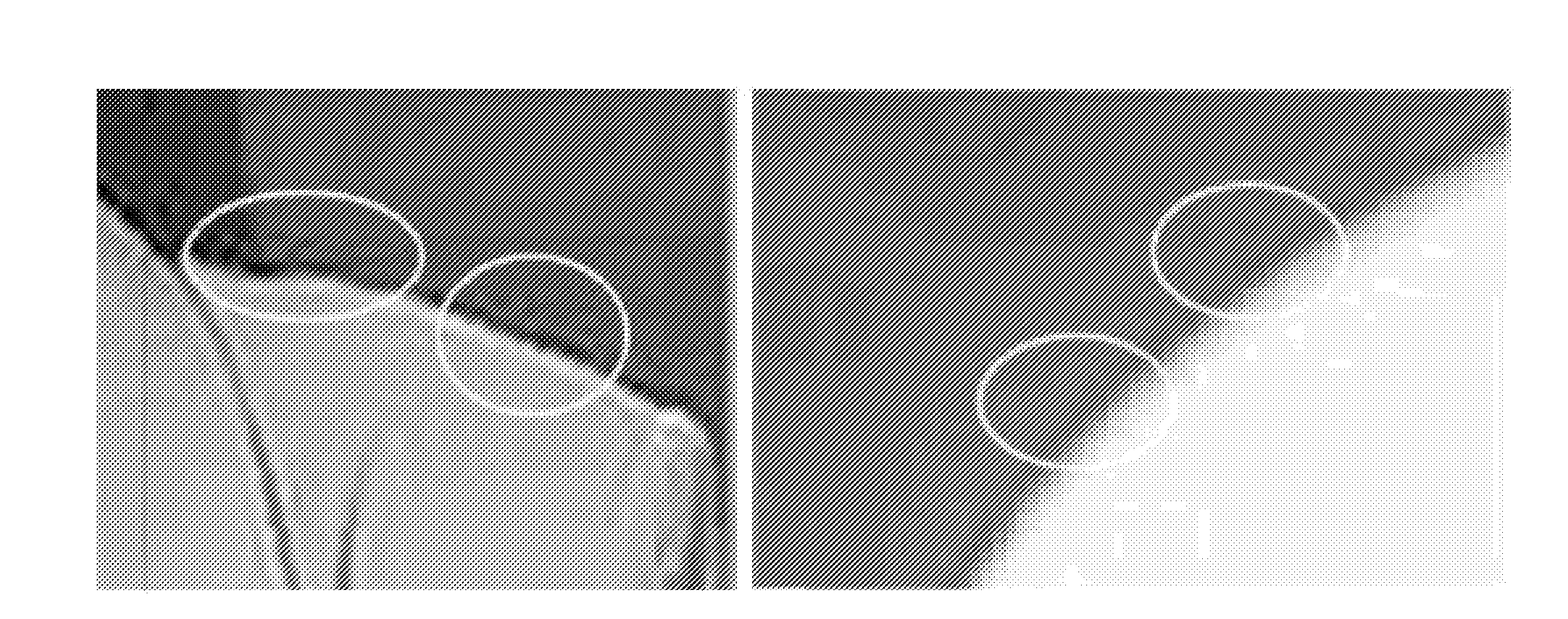
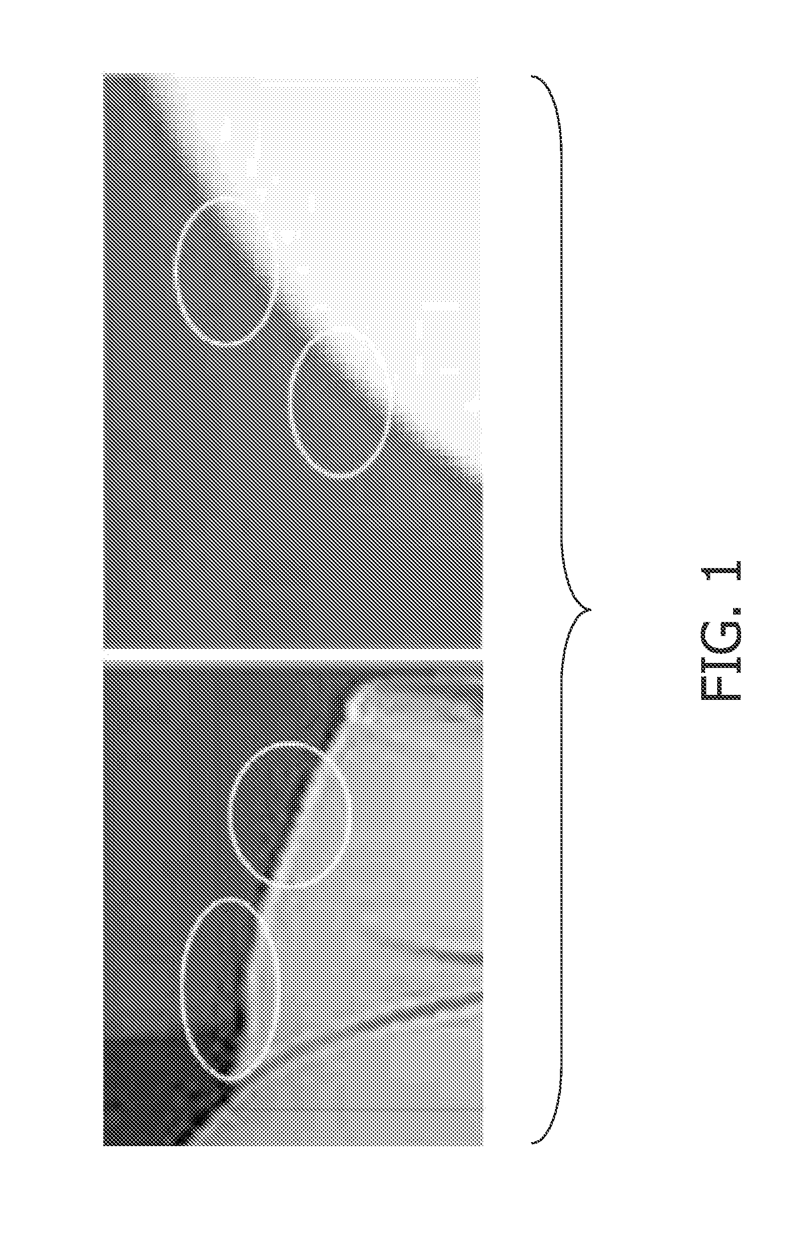
[0095]In FIG. 1 the exemplifying picture demonstrates the inventive perception that ringing artefacts predominantly occur around strong object edges. The light ovals indicate some of the blocks affected by ringing.

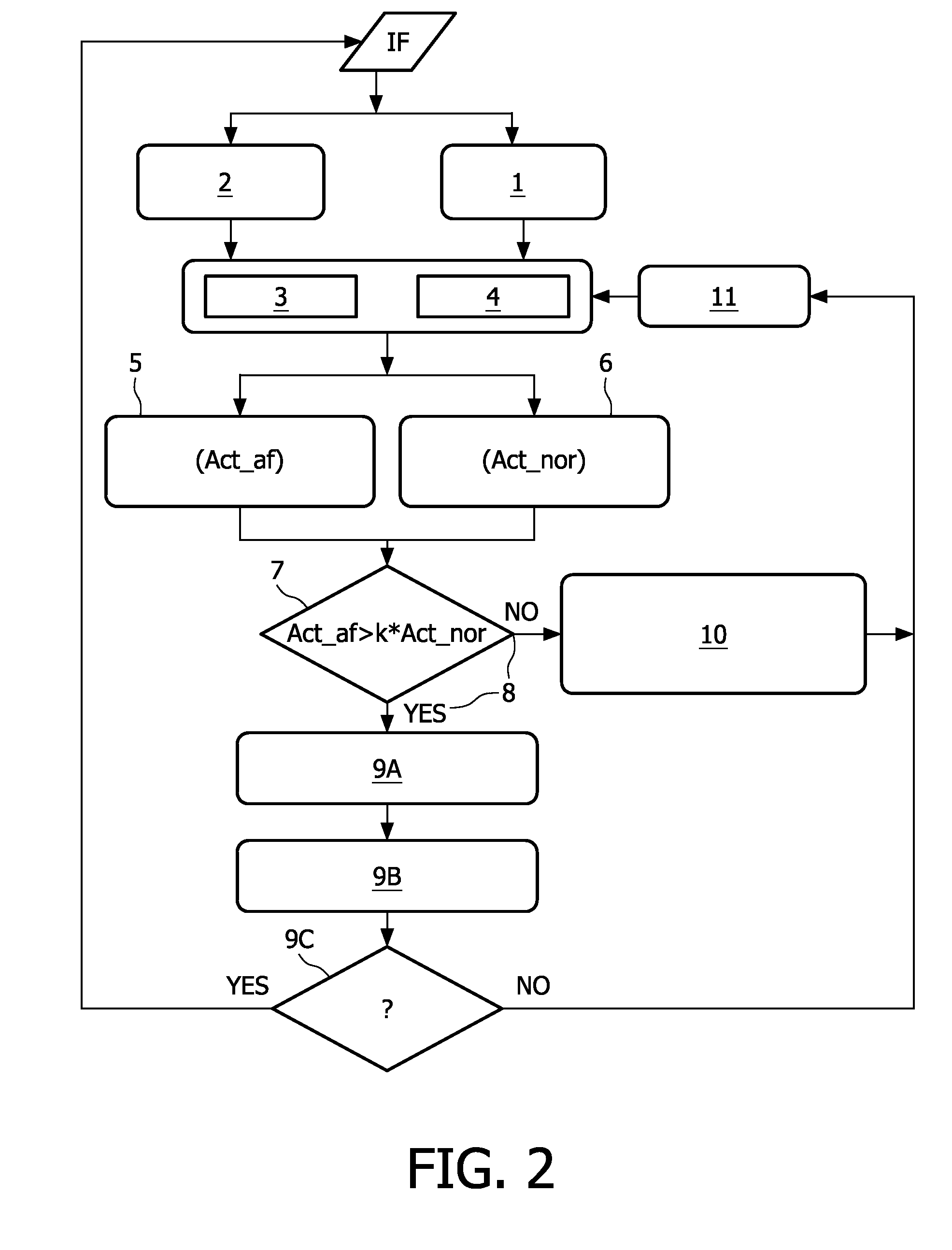
[0096]FIG. 2 shows a flow-block-scheme of a preferred embodiment of an algorithm for the method according to the inventive concept. The same FIG. 2 may also serve as sufficient disclosure for a respective filter device, which basically functions according to the illustrated method, and a respective data signal, which is basically a result of the illustrated method. The algorithm of this embodiment comprises the following main steps after providing a picture e.g. an input frame IF:

[0097]1. Determining a grid of pixel blocks on a picture. The algorithm can exploit the grid position information from the actual bit-stream of the input frame IF, or in modified embodiments, additionally or alternatively, from the compressed bit-stream, if such is available during the artefact re...


PUM


Abstract

The invention proposes a method (FIG. 2) and respective devices (FIG. 2) and software for an algorithm to detect and remove ringing artefacts and mosquito noise in decompressed pictures and video. The proposed idea is based on the observation that ringing is spatially localized within a block, which contains at least a part of an object edge, in particular a strong object edge. Blocks affected by ringing are detected by analyzing (1) a block grid position, location (2) of an object edge and by comparing (7) local spatial activities (Act af, Act nor) of adjacent blocks, i.e. affected blocks and nor) not-affected blocks.

Description

FIELD OF THE INVENTION[0001]The invention relates to a method of processing data, which represent at least one picture potentially affected by artefacts due to transform coding.[0002]The invention also relates to a coding device being adapted for executing the steps of the method and a respective data signal and respective implementations thereof. The invention leads to an encoder device, a decoder device, a display device and a respective apparatus.[0003]The invention also relates to a computer program product and a storage medium readable by a computing device.BACKGROUND OF THE INVENTION[0004]Coding a picture or a sequence of pictures comprises different steps. Each picture is composed of a bidimensional array of picture elements or pixels, each of them having luminance and chrominance components. For encoding purposes, the picture is subdivided into non-overlapping blocks of pixels. A so-called discrete cosine transform (DCT) can be applied to each block of the picture. The coeff...

Claims


Application Information

Patent Timeline
Patent Type & Authority Applications(United States)
IPC IPC(8): G06K9/40
CPCH04N5/142H04N5/21G06T5/002G06T5/10H04N19/86H04N19/176H04N19/117H04N19/14H04N19/186G06T5/20
Inventor KIRENKO, IHOR O.SEDZIN, ALIAKSEI V.
Owner PACE PLC
Why Eureka
Try Eureka