Indexable milling insert

a technology of inserts and milling, applied in the direction of turning machine accessories, shaping cutters, manufacturing tools, etc., can solve the problems of affecting the quality of the finished product, the risk of vibration, and the failure of the tool or machine, etc., and achieve the effect of simple technology

a technology of inserts and milling, applied in the direction of turning machine accessories, shaping cutters, manufacturing tools, etc., can solve the problems of affecting the quality of the finished product, the risk of vibration, and the failure of the tool or machine, etc., and achieve the effect of simple technology

US20100003090A1Active Publication Date: 2010-01-07SANDVIK INTELLECTUAL PROPERTY AB

Image

  • Indexable milling insert
  • Indexable milling insert
  • Indexable milling insert

Examples


Embodiment Construction

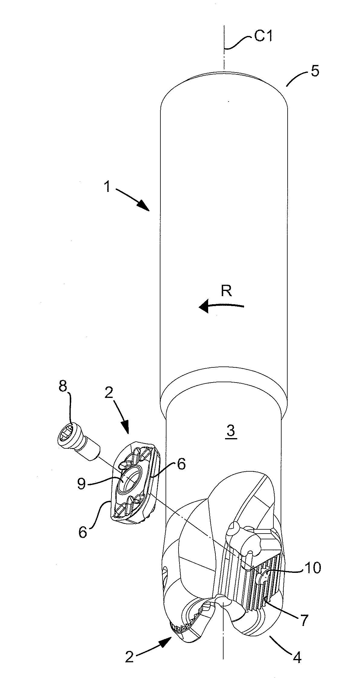
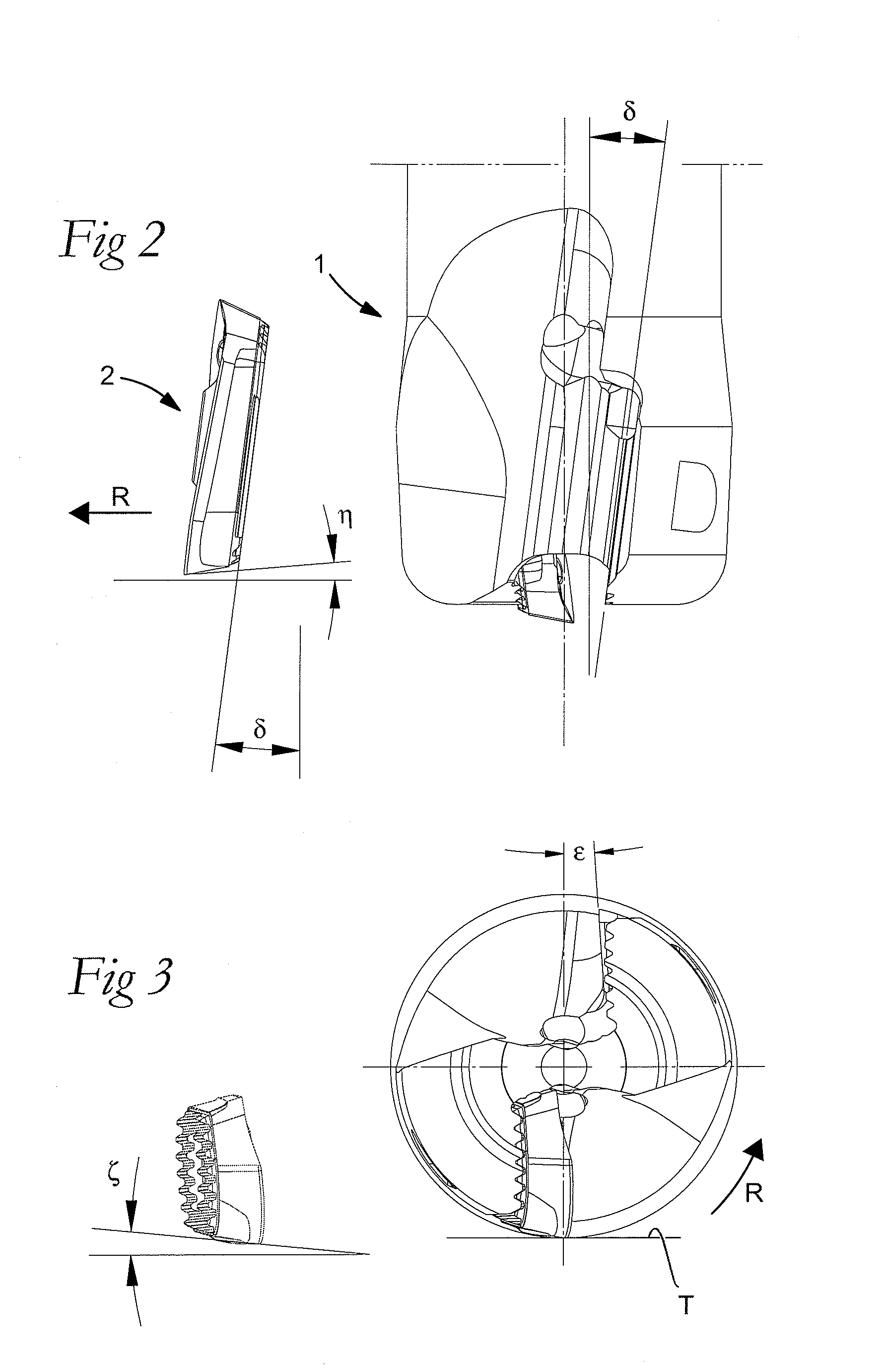
[0024]Before exemplifying embodiments of the invention are described in more detail, some concepts for the understanding of the nature of the invention should be made clear. Thus, the concept “nominal” clearance angle means that the angle in question only relates to the proper milling insert, i.e., without association to the basic body of the milling cutter. However, if a clearance angle is “effective”, reference is made to the angle formed by the same clearance surface in relation to an imaginary cylinder concentric with the center axis of the milling cutter body and touched by the main edge of the milling insert adjacent to the clearance surface.

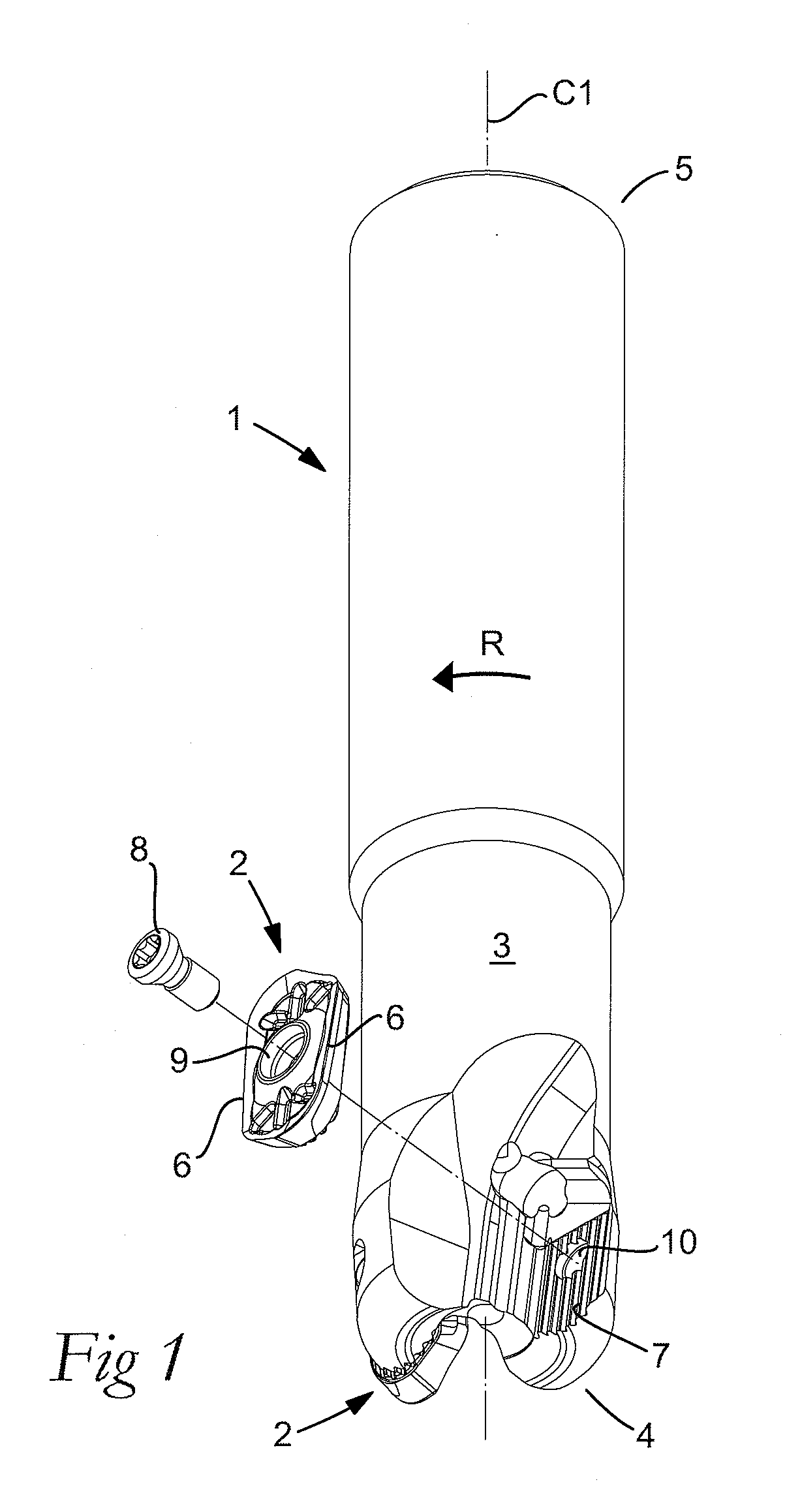
[0025]Furthermore, the concepts “tipping-in” and “tipping-in angle” are used to define the spatial position of the mounted milling insert in the milling cutter body. In practice, this position is determined by how the bottom in that seating of the milling cutter body in which the milling insert is fixed is situated in relation to the cente...


PUM

PropertyMeasurementUnit
widthaaaaaaaaaa
clearance angleaaaaaaaaaa
cutting edge angleaaaaaaaaaa

Abstract

An indexable milling insert, including an upperside, an underside parallel to an imaginary reference plane, and two cutting edges. Each cutting edge includes a cutting edge line and is formed between a chip surface included in the upperside and a first clearance surface extending between the upperside and the underside, the first clearance surface forming an acute, nominal first clearance angle (α) with a normal to the reference plane. Each cutting edge includes a main edge, which is at least partly convexly curved as viewed in plane elevation from above, and which extends from an initial end, which determines the maximal cutting depth of the milling insert, to a corner edge having a radius of curvature that is smaller than the radius of curvature of the main edge, the main edge rising in the direction from the initial end toward the corner edge such that the distance thereof to the underside successively increases in the direction. A second clearance surface is formed between the cutting edge line and the first clearance surface, the second clearance surface having a width of at most 0.3 mm and a nominal second clearance angle (λ) that is smaller than the first clearance angle. The second clearance surface is of uniform width and the second clearance angle decreases successively in the direction from the initial end toward the corner edge.

Description

[0001]This application claims priority under 35 U.S.C. § 119 to Swedish Patent Application No. 0801629-7, filed on Jul. 7, 2008, which is incorporated by reference herein in its entirety.FIELD OF THE INVENTION[0002]The present invention relates generally to an indexable milling insert of the type that includes an upperside, an underside parallel to an imaginary reference plane, and two cutting edges, which individually include a cutting edge line and are formed between a chip surface included in the upperside and a first clearance surface extending from the upperside toward the underside. The clearance surface forms an acute, nominal first clearance angle with an arbitrary normal to the reference plane. The individual cutting edge includes a main edge, which is at least partly convexly curved as viewed in plane elevation from above, and which extends from an initial end that determines the maximal cutting depth of the milling insert, to a corner edge having a radius of curvature tha...

Claims


Application Information

Patent Timeline
07 Jan 2010
Publication
US20100003090A1
IPC
B23P15/28
CPC
B23C5/202; B23C2200/125; B23C2200/165; Y10T407/1924; B23C2210/0407; Y10T407/23; Y10T407/1936; B23C2200/286
Inventors
JOHANSSON; LILJEREHN, ANDERS