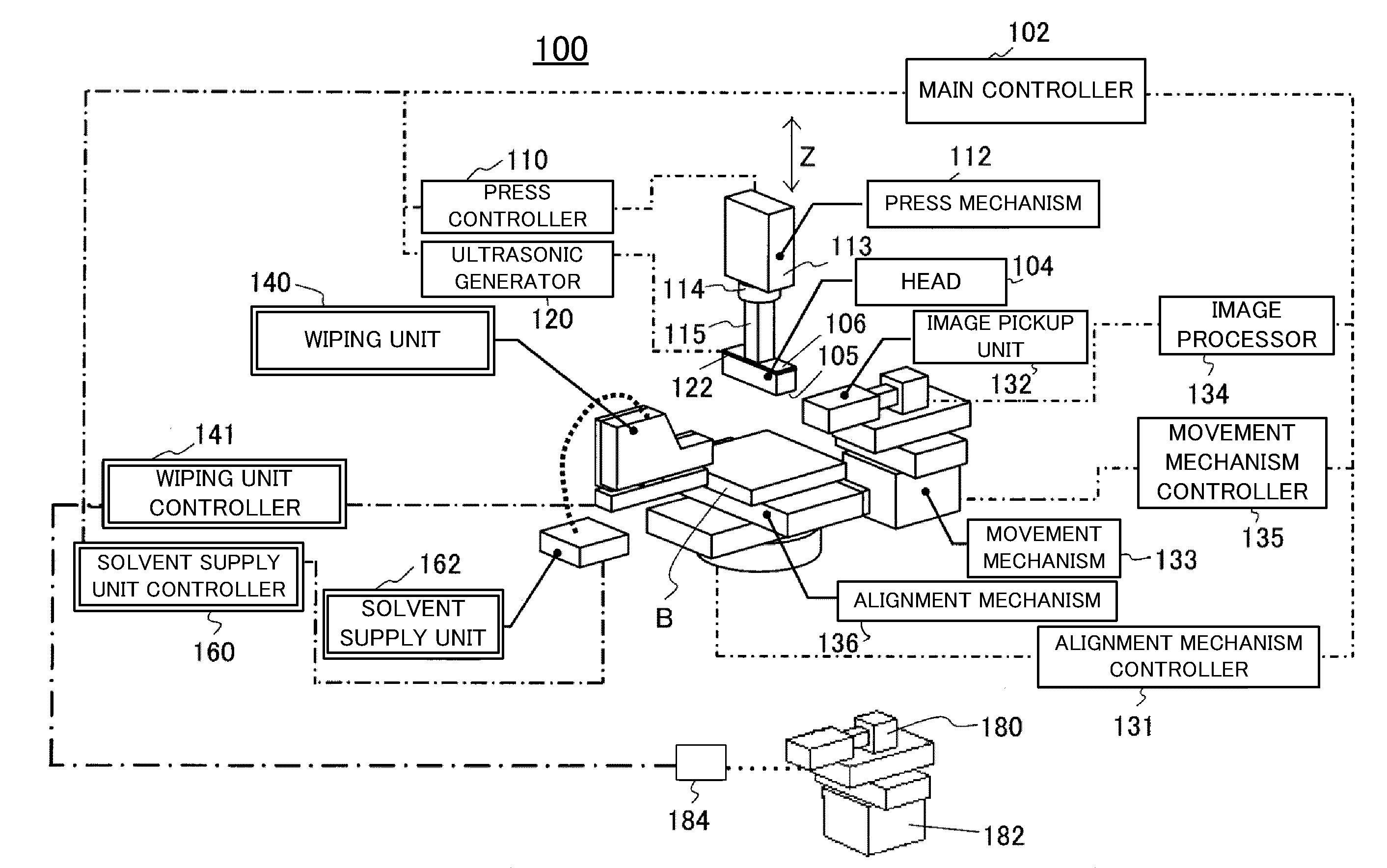
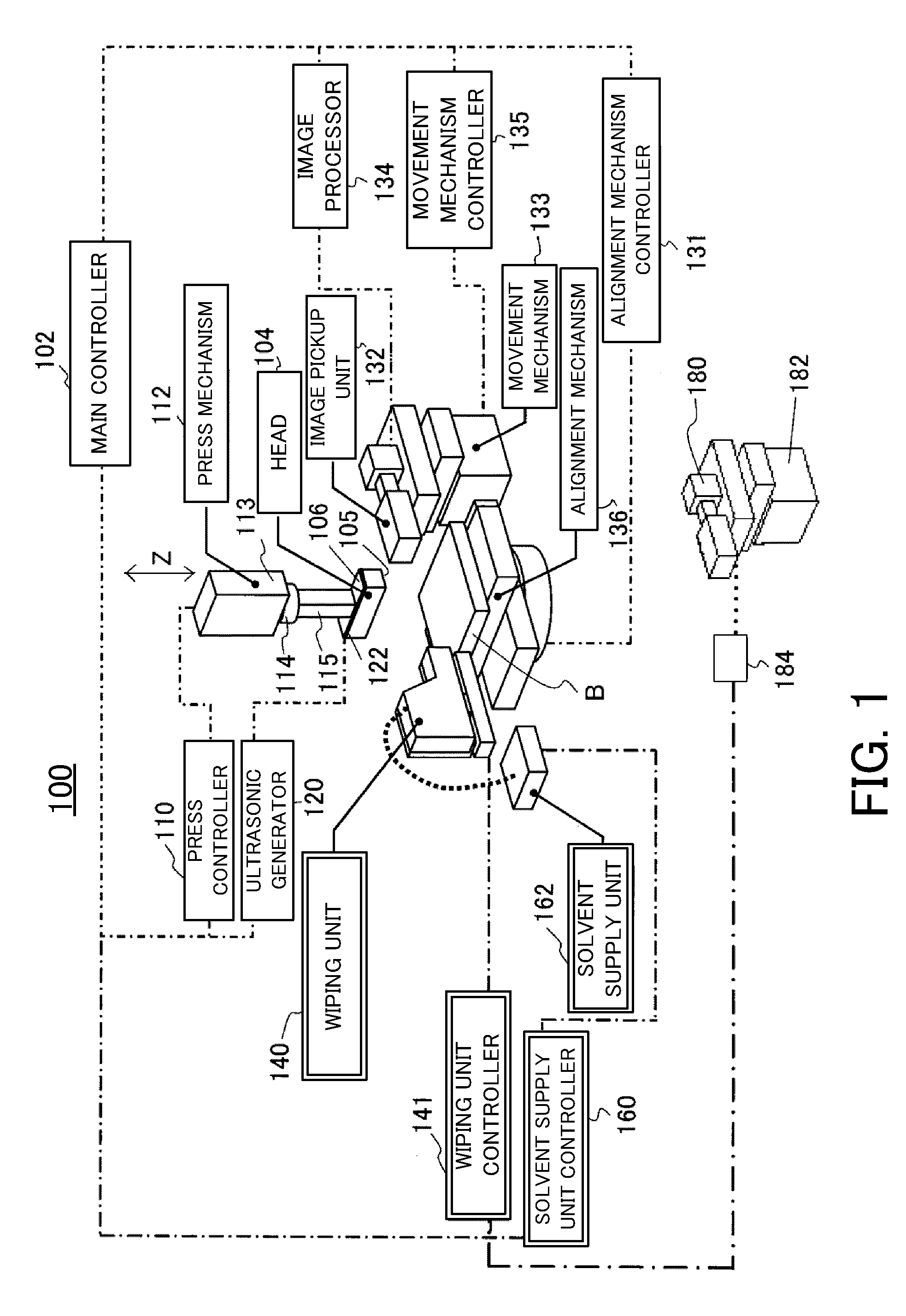
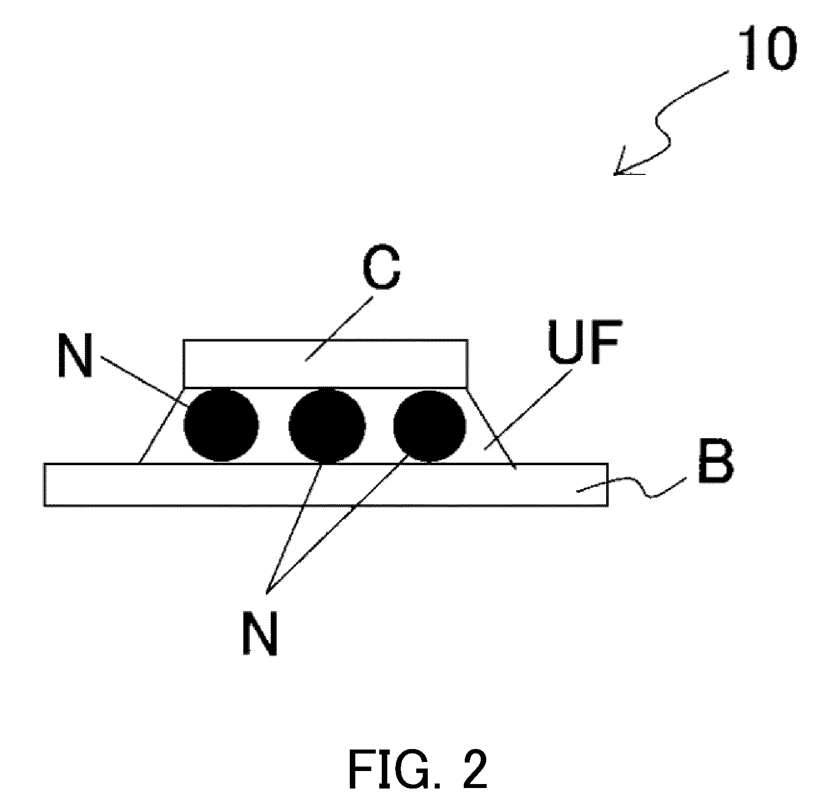
[0011]An ultrasonic bonding apparatus according to one aspect of the present invention used to manufacture an electronic device that includes a substrate, an electronic component, and an underfill that is filled in a space between the electronic component and the substrate includes a head that includes a tool surface configured to
mount the electronic component, a wiping unit configured to wipe out pre-cured underfill that has adhered to the tool surface of the head, by using a wiping member on a wiping table, an ultrasonic bonding unit configured to ultrasonically bond the electronic component with the substrate and to press the head against the wiping member on the wiping table, a
detector configured to detect a first pressure applied between the wiping member on the wiping table and the tool surface when the wiping unit provides wiping, and a controller configured to control a second pressure applied by the ultrasonic bonding unit, based on a detection result by the detector. This ultrasonic bonding apparatus can maintain the properly set pressure, improve the wiping performance, and maintain the tool surface clean.
[0012]An ultrasonic bonding apparatus according to another aspect of the present invention used to manufacture an electronic device that includes a substrate, an electronic component, and an underfill that is filled in a space between the electronic component and the substrate includes a head that includes a tool surface configured to mount the electronic component, a wiping unit configured to wipe out pre-cured underfill that has adhered to the tool surface of the head, by using a wiping member on a wiping table, the wiping unit including a
solvent supply unit configured to supply a
solvent configured to
powder the underfill, to the wiping member on the wiping table, an ultrasonic bonding unit configured to ultrasonically bond the electronic component with the substrate and to press the head against the wiping member on the wiping table, a detector configured to detect a pressure applied between the wiping member on the wiping table and the tool surface when the wiping unit provides wiping, and controller configured to control a
solvent supply amount by the solvent supply unit, based on a detection result by the detector. This ultrasonic bonding apparatus can maintain a solvent supply amount appropriate to the wiping member, improve the wiping performance, and maintain the tool surface clean.
[0013]An ultrasonic bonding apparatus according to still another aspect of the present invention used to manufacture an electronic device that includes a substrate, an electronic component, and an underfill that is filled in a space between the electronic component and the substrate includes a head that includes a tool surface configured to mount the electronic component, a wiping unit configured to wipe out pre-cured underfill that has adhered to the tool surface of the head, by using a wiping member on a wiping table, the wiping unit including a feed mechanism that includes a motor and is configured to supply the wiping member to the wiping table and to roll up the wiping member from the wiping table, an ultrasonic bonding unit configured to ultrasonically bond the electronic component with the substrate, a detector configured to detect a variation of a torque of the motor, and a controller configured to determine whether a residual amount of the wiping member is sufficient, based on a detection result by the detector. This ultrasonic bonding apparatus can recognize a residual amount of the wiping member, avoid wiping when there is no wiping member, and maintains the tool surface clean.
[0014]An ultrasonic bonding apparatus according to another aspect of the present invention used to manufacture an electronic device that includes a substrate, an electronic component, and an underfill that is filled in a space between the electronic component and the substrate includes a head that includes a tool surface configured to mount the electronic component, a wiping unit configured to wipe out pre-cured underfill that has adhered to the tool surface of the head, by using a wiping member on a wiping table, an ultrasonic bonding unit configured to ultrasonically bond the electronic component with the substrate, a detector configured to detect a
dirt state on the tool surface by taking an image of a surface of the electronic component that has been bonded with the substrate, and a controller configured to control wiping timing by the wiping unit, based on a detection result by the detector. This ultrasonic bonding apparatus can perform when the tool surface is dirty, and maintain the tool surface clean. When the tool surface is not dirty, the controller can avoid wiping and maintain the
throughput of the ultrasonic bonding.

