Containers having radio frequency identification tags and method of applying radio frequency identification tags to containers

a technology of radio frequency identification and container, applied in the field of containers with radio frequency identification tags, can solve the problems of extremely limited information that can be written on the label of bar code, design challenges with respect to both containers and bar code readers, and the possibility of counterfeiting, so as to reduce facilitate the effect of carrying out and reducing the risk of counterfeiting

Inactive Publication Date: 2010-01-14
ABBOTT LAB INC
View PDF25 Cites 57 Cited by
  • Summary
  • Abstract
  • Description
  • Claims
  • Application Information

AI Technical Summary

Benefits of technology

[0016]In one embodiment, the container has a radio frequency identification tag affixed thereto. The container comprises a mouth, a neck, a body, and a bottom. The container can also have a closure, a septum, or an adapter for other components of an automated clinical analyzer. The neck is capable of receiving a closure. A stud projecting from the bottom of the container, preferably the center of the bottom of the container, serves to retain the radio frequency identification during the attachment of the radio frequency identification tag to the container. A radio frequency identification tag protector can be used to provide protection for the radio frequency identification tag. After the attachment of a radio frequency identification tag to the container, the radio frequency identification tag protector protects the radio frequency identification tag from damage during shipping, storage, and handling. The radio frequency identification tag protector can also function as a base to enable the container to rest on a flat surface of the type that may be encountered in a medical instrument, such as, for example, a radio frequency identification reader, automatic conveyor belt, surface heater, etc.
[0017]In another embodiment, the aforementioned stud projecting from the bottom of the container is replaced by a radio frequency identification tag retainer, which serves to retain the radio frequency identification during the attachment of the radio frequency identification tag to the container.
[0023]Deforming the stud or the radio frequency identification tag retainer to secure the radio frequency identification tag is non-reversible, simple, fast, and easy to carry out by automated equipment. Attempts to remove the radio frequency identification tag will either damage the radio frequency identification tag or the container or both. Thus, the assembly of the container and the radio frequency identification tag can be used to prevent, or at least greatly reduce, counterfeiting of the medical product.

Problems solved by technology

An unobstructed optical path is required in order to read a bar code label, which requirement results in design challenges with respect to both the container and bar code readers.
Bar code labels generally have only a limited quantity of space, with the result that the quantity of information that can be written on a bar code label is extremely limited.
Bar code labels can be removed and reused, thereby leading to the possibility of counterfeiting.
The current method of attaching radio frequency identification tags to containers, i.e., by means of a pressure-sensitive adhesive provides a low degree of adhesive strength and detracts from aesthetics, and increases the likelihood of counterfeiting, i.e., radio frequency identification tags can be removed and attached to counterfeit products.
These drawbacks include the requirement of complex, and, consequently, costly, molds, the difficulty of mass production, the difficulty of implementing robotics, and the difficulty of the selection of compatible materials.
However, active and semi-passive radio frequency identification tags are more expensive than are passive radio frequency identification tags, thereby making their cost too expensive for objects having a low value.
The most critical obstacle for utilizing radio frequency identification tags is high cost.
The cost of microchips and the assembly processes associated with radio frequency identification tags is high relative to the cost of typical diagnostic products.
Radio frequency identification tags will be expensive, unless they can be mass-produced and applied to diagnostic products by means of a highly efficient automated process.
In addition, counterfeiting can be carried out by removing the proper radio frequency identification tag and reattaching an improper radio frequency identification tag.
Appearance of the container is also problematic, because attachment of radio frequency identification tags to containers results in a bumpy surface and a surface having a poor appearance.
Still another problem is delamination of the radio frequency tag from the container.
The scrap rate of a process for applying radio frequency identification tags to containers is high on account of the difficulty inherent in the placement of a microchip on the contacts of an antenna.
Finally, liquid content in the containers of diagnostic product diminishes the signal of radio frequency; therefore, the placement of radio frequency identification tags for diagnostic products containing liquids is highly restricted.
However, tags can be detached under harsh environmental conditions, such as low temperatures or high humidity during shipping and storage.
The capital cost involving the robotic setup for placing the tag during forming process is high.
The embodiment including hot melt adhesive to assist attachment poses additional challenges of mechanical and thermal controls during tag placement.
The cost of capital expenditure is expensive for such mechanical arrangements.
The other disadvantage is that for thin-walled containers or small containers, the area and the thickness of the radio frequency identification tag renders the insert-molding process unfeasible.

Method used


Image

  • Containers having radio frequency identification tags and method of applying radio frequency identification tags to containers
  • Containers having radio frequency identification tags and method of applying radio frequency identification tags to containers
  • Containers having radio frequency identification tags and method of applying radio frequency identification tags to containers

Examples


Embodiment Construction

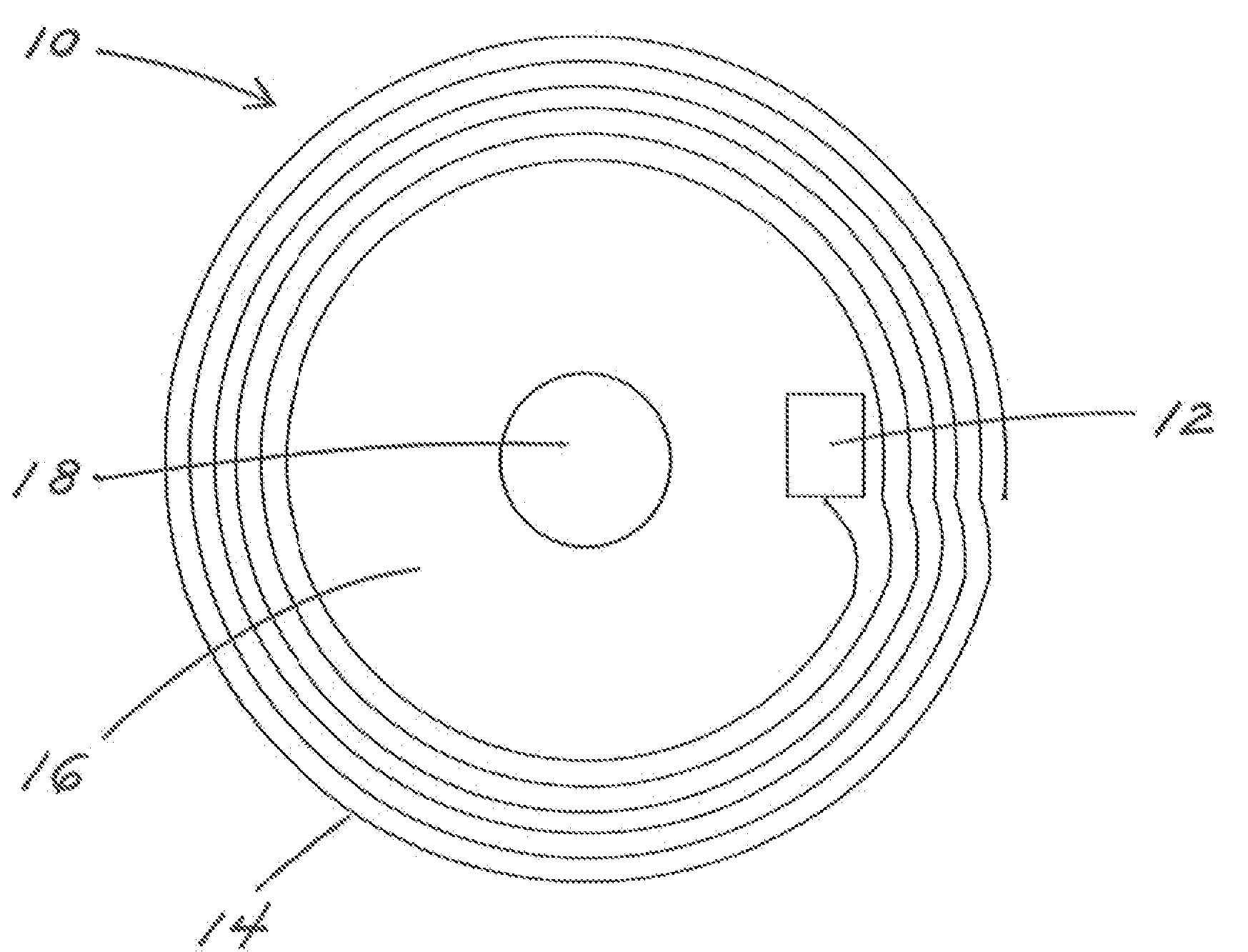
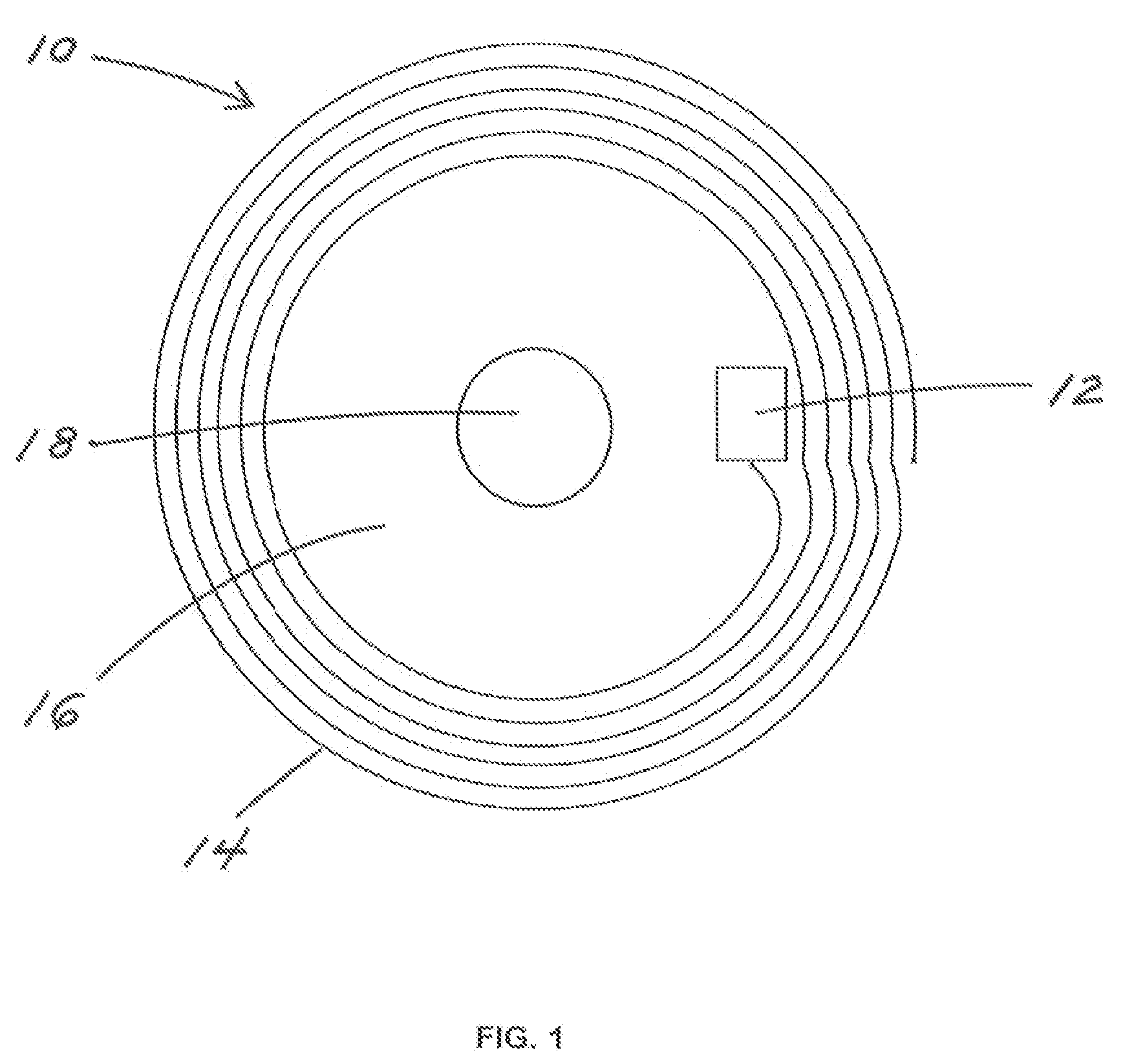
[0036]As used herein, the expression “radio frequency identification system” means a system comprising a radio frequency identification tag made up of a microchip with an antenna, and a radio frequency identification interrogator or radio frequency identification reader with an antenna. The radio frequency identification reader sends out electromagnetic waves. The antenna of the radio frequency identification tag is tuned to receive these waves. A passive radio frequency identification tag draws power from the field created by the reader and uses it to power the circuits of the microchip. The microchip then modulates the waves that the passive radio frequency identification tag sends back to the radio frequency identification reader, which converts the waves received by the radio frequency identification reader into digital data.

[0037]As used herein, the term “microchip” means a miniaturized electronic circuit that has been manufactured on the surface of a thin substrate of semicond...


PUM


Abstract

A container having a radio frequency identification tag attached thereto by means of a stud or a radio frequency identification tag retainer_projecting from the exterior surface of the container. The container can be used to contain medical products, and the container can be of various types, such as, for example, a bottle, a micro-well plate, a cartridge, a tube. In one embodiment, the container has a radio frequency identification tag affixed thereto. The container comprises a mouth, a neck, a body, and a bottom. The container can also have a closure, a septum, or an adapter for other components of an automated clinical analyzer. The neck is capable of receiving a closure. A stud or a radio frequency identification tag retainer projecting from the bottom of the container, preferably the center of the bottom of the container, serves to retain the radio frequency identification during the attachment of the radio frequency identification tag to the container. A radio frequency identification tag protector can be used to provide protection for the radio frequency identification tag.

Description

BACKGROUND OF THE INVENTION[0001]1. Field of the Invention[0002]This invention relates to containers for products, more particularly containers having radio frequency identification tags and methods for applying radio frequency identification tags to containers.[0003]2. Discussion of the Art[0004]In the area of medical diagnostics, and, more particularly, in the area of medical diagnostics that uses automated clinical analyzers, bar code labels are generally used to identify containers, such as, for example, reagent containers. Bar code labels can be applied to the surface of the container by means of various processes, such as, for example, printing. An unobstructed optical path is required in order to read a bar code label, which requirement results in design challenges with respect to both the container and bar code readers. The bar code label must be clear, i.e., the print quality thereof must be satisfactory and the label must be free from opaque foreign material, such as, for ...

Claims


Application Information

Patent Timeline
Patent Type & Authority Applications(United States)
IPC IPC(8): G08B13/14
CPCB01L2300/0851B01L3/545B01L2200/16B01L2200/12B01L2300/0829G06K19/041G06K19/07749B65D23/14B01L3/5453Y10T428/13Y10T428/24B01L9/06B01L2300/022B65D2203/10
Inventor YANG, TAHUABEREK, MICHAEL A.
Owner ABBOTT LAB INC
Why Eureka
Try Eureka