Magnetoresistance effect element and MRAM
- Summary
- Abstract
- Description
- Claims
- Application Information
AI Technical Summary
Benefits of technology
Problems solved by technology
Method used
Image
Examples
first exemplary embodiment
1. First Exemplary Embodiment
1-1. Structure
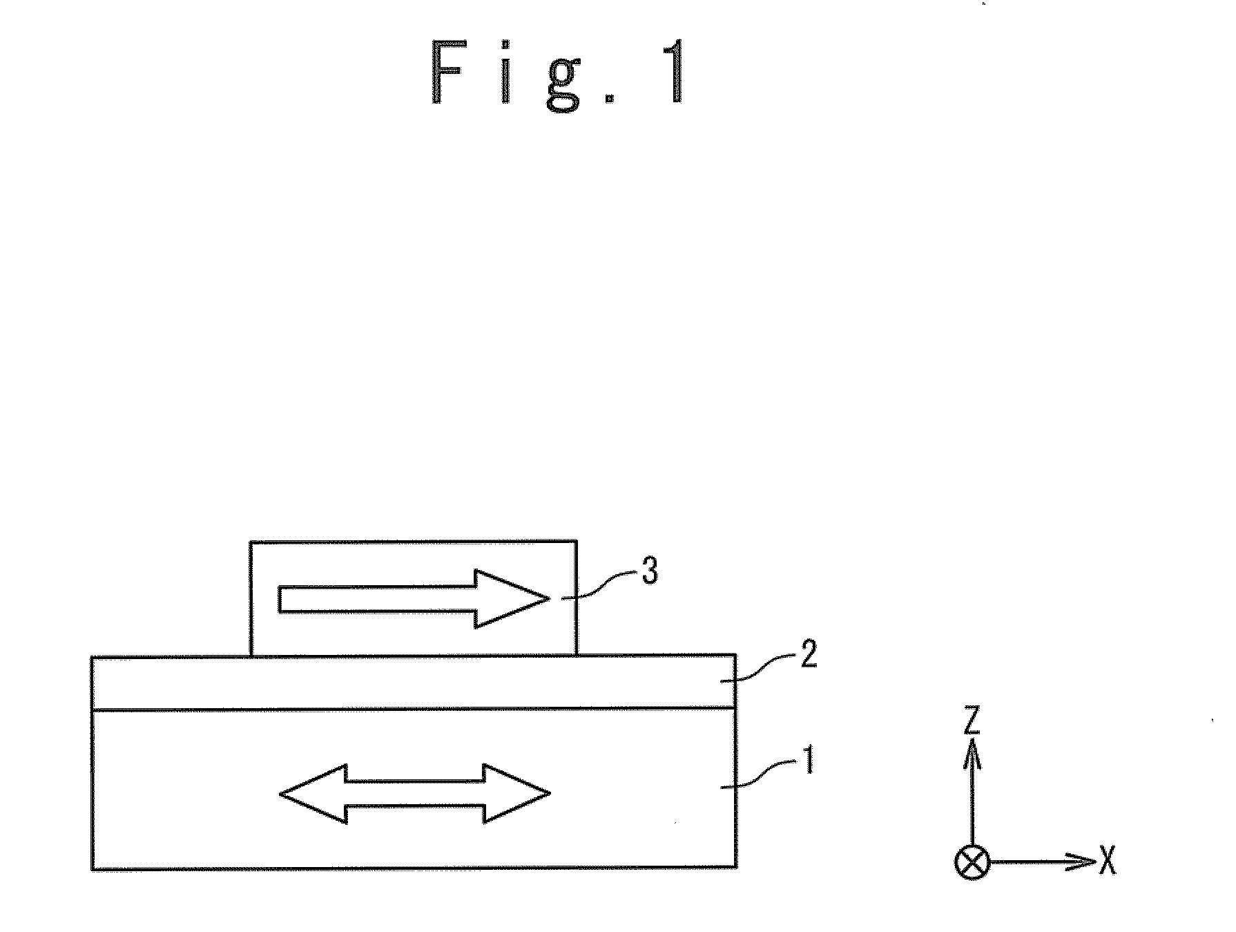
[0043]FIG. 1 is a side view schematically showing a structure of a magnetoresistance effect element according to a first exemplary embodiment. The magnetoresistance effect element has a stacked structure in which a magnetization free layer 1, a tunnel barrier layer 2 and a magnetization fixed layer 3 are sequentially stacked. In FIG. 1, the stack direction is defined as a “Z direction”. That is, a direction perpendicular to a principal surface of each layer is the Z direction. Each layer is formed on an XY plane perpendicular to the Z direction.
[0044]The magnetization free layer (free layer) 1 includes a ferromagnetic layer. Also, as will be described in detail later, the magnetization free layer 1 has a region whose magnetization direction is reversible.
[0045]The tunnel barrier layer 2 is a nonmagnetic layer. For example, the tunnel barrier layer 2 is formed of an insulating film. The tunnel barrier layer 2 is sandwiched between the magnet...
second exemplary embodiment
2. Second Exemplary Embodiment
[0077]In a second exemplary embodiment, the same reference numerals are given to the same components as those described in the first exemplary embodiment, and an overlapping description will be omitted as appropriate.
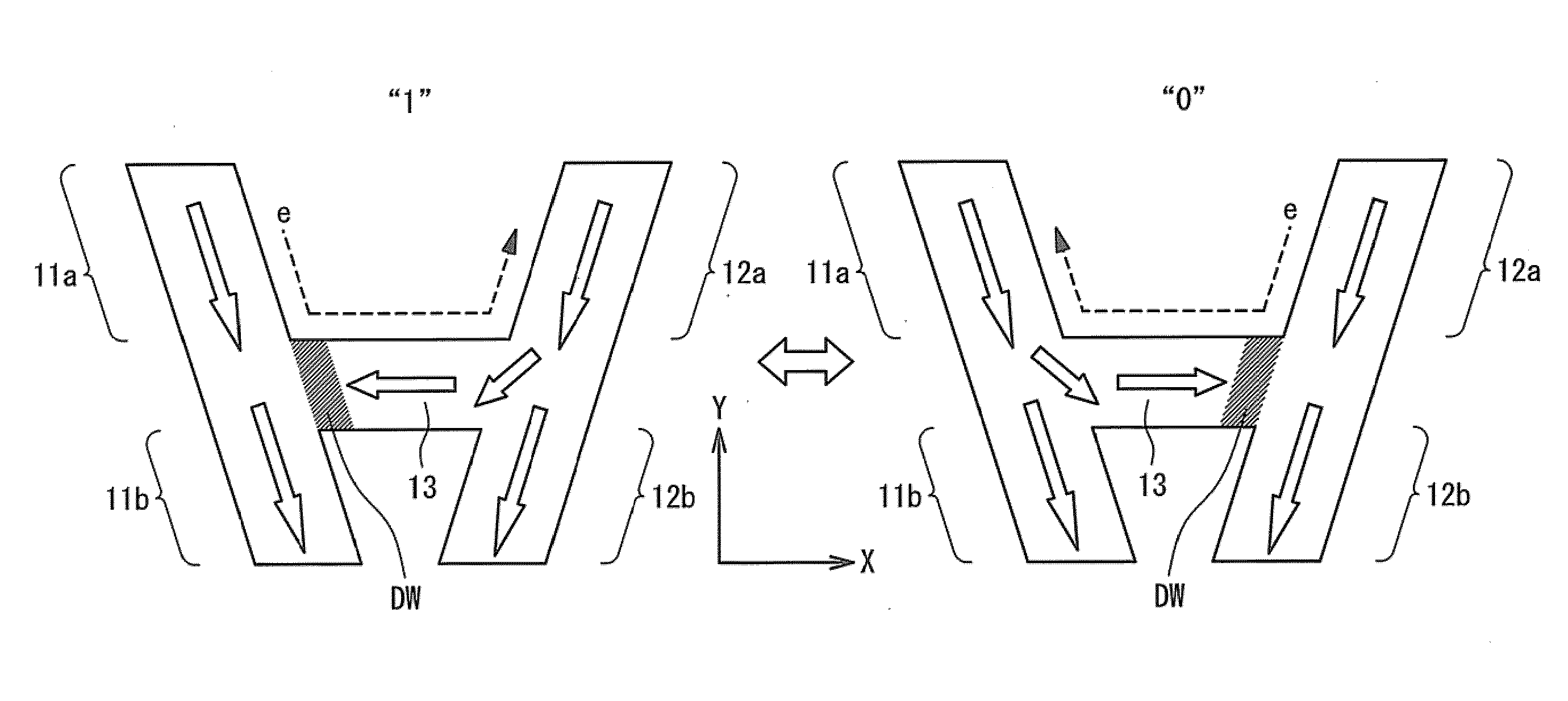
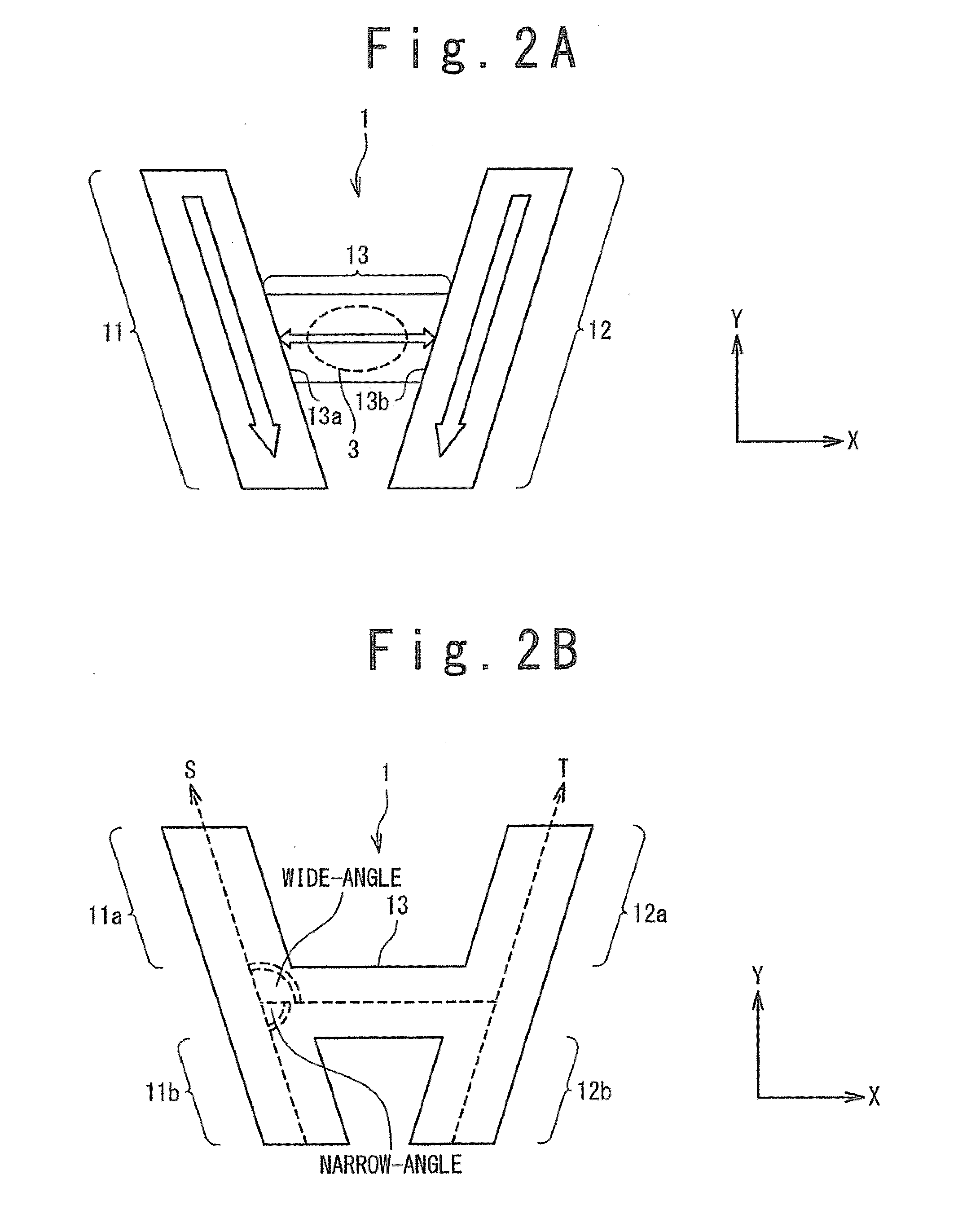
[0078]FIG. 6 is a plan view showing a structure of the magnetization free layer 1 according to the second exemplary embodiment. In the present exemplary embodiment, the S-axis alone which the first magnetization fixed region 11 is formed and the T-axis along which the second magnetization fixed region 12 is formed are almost parallel to each other. Also, the first magnetization fixed region 11 and the second magnetization fixed region 12 are rotationally symmetric to each other around the magnetization switching region 13. The wide-angle section 11a of the first magnetization fixed region 11 faces to the narrow-angle section 12b of the second magnetization fixed region 12, and the narrow-angle section 11b of the first magnetization fixed re...
third exemplary embodiment
3. Third Exemplary Embodiment
[0082]In a third exemplary embodiment, the same reference numerals are given to the same components as those described in the foregoing exemplary embodiments, and an overlapping description will be omitted as appropriate.
[0083]FIG. 8 is a side view schematically showing a structure of the magnetoresistance effect element according to the third exemplary embodiment. According to the present exemplary embodiment, the magnetization free layer 1 has a plurality of ferromagnetic layers magnetically coupled to each other. For example, in FIG. 8, the magnetization free layer 1 has a stacked structure in which a first magnetization free layer 1a, a nonmagnetic layer 20 and a second magnetization free layer 1b are sequentially stacked. Among them, the second magnetization free layer 1b is in contact with the tunnel insulating layer 2. The first magnetization free layer 1a and the second magnetization free layer 1b are connected through the nonmagnetic layer 20 an...
PUM
 Abstract
Description
Claims
Application Information
 - R&D
- Intellectual Property
- Life Sciences
- Materials
- Tech Scout
- Unparalleled Data Quality
- Higher Quality Content
- 60% Fewer Hallucinations
Browse by: Latest US Patents, China's latest patents, Technical Efficacy Thesaurus, Application Domain, Technology Topic, Popular Technical Reports.
© 2025 PatSnap. All rights reserved.Legal|Privacy policy|Modern Slavery Act Transparency Statement|Sitemap|About US| Contact US: help@patsnap.com


