
Power control system for a wireless communication unit

a wireless communication unit and power control technology, applied in the direction of antennas, antennas with semiconductor devices/discharge tubes, electric long antennas, etc., can solve the problems of high nonlinearity of the loop, affecting the performance of spectral emission, and unable to control the linear closed loop control system

Inactive Publication Date: 2010-01-14
NORTH STAR INNOVATIONS
View PDF26 Cites 25 Cited by
  • Summary
  • Abstract
  • Description
  • Claims
  • Application Information

AI Technical Summary

Problems solved by technology

Furthermore, in a number of wireless communication systems, the effect of fast fading in the communication channel is a known and generally undesirable phenomenon caused by the signal arriving at a receiver via a number of different paths.
It is known that, within the field of power control techniques, closed loop control systems are widely adopted but suffer from the following problems:(i) With the power amplifier (PA) fully off, and with no radio frequency (RF) output the loop is in a highly nonlinear state and cannot be controlled by a linear closed loop control system.
However, application of a log detector as the power detection mechanism will distort the desired raised cosine profile at the PA output and compromise spectral emission performance.
In addition, the more complex waveform used with a peak detector typically needs to be calibrated / phased in the factory with respect to output target power.
Thus, critical standards' test specifications may be failed if accurate control of ramp generation and PA activation / turn on is not achieved, such as:(i) Power versus time (PvT), or(ii) Out-of-band spectral emission performance.

Method used


Image

  • Power control system for a wireless communication unit
  • Power control system for a wireless communication unit
  • Power control system for a wireless communication unit

Examples


Embodiment Construction

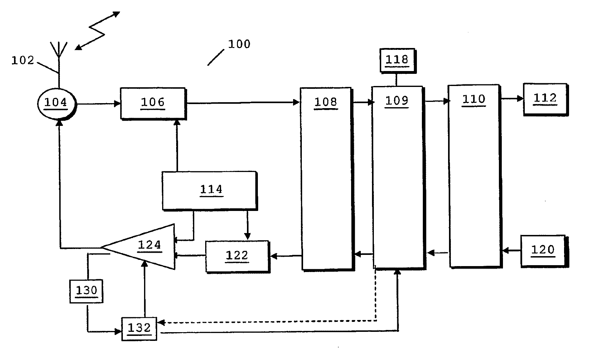
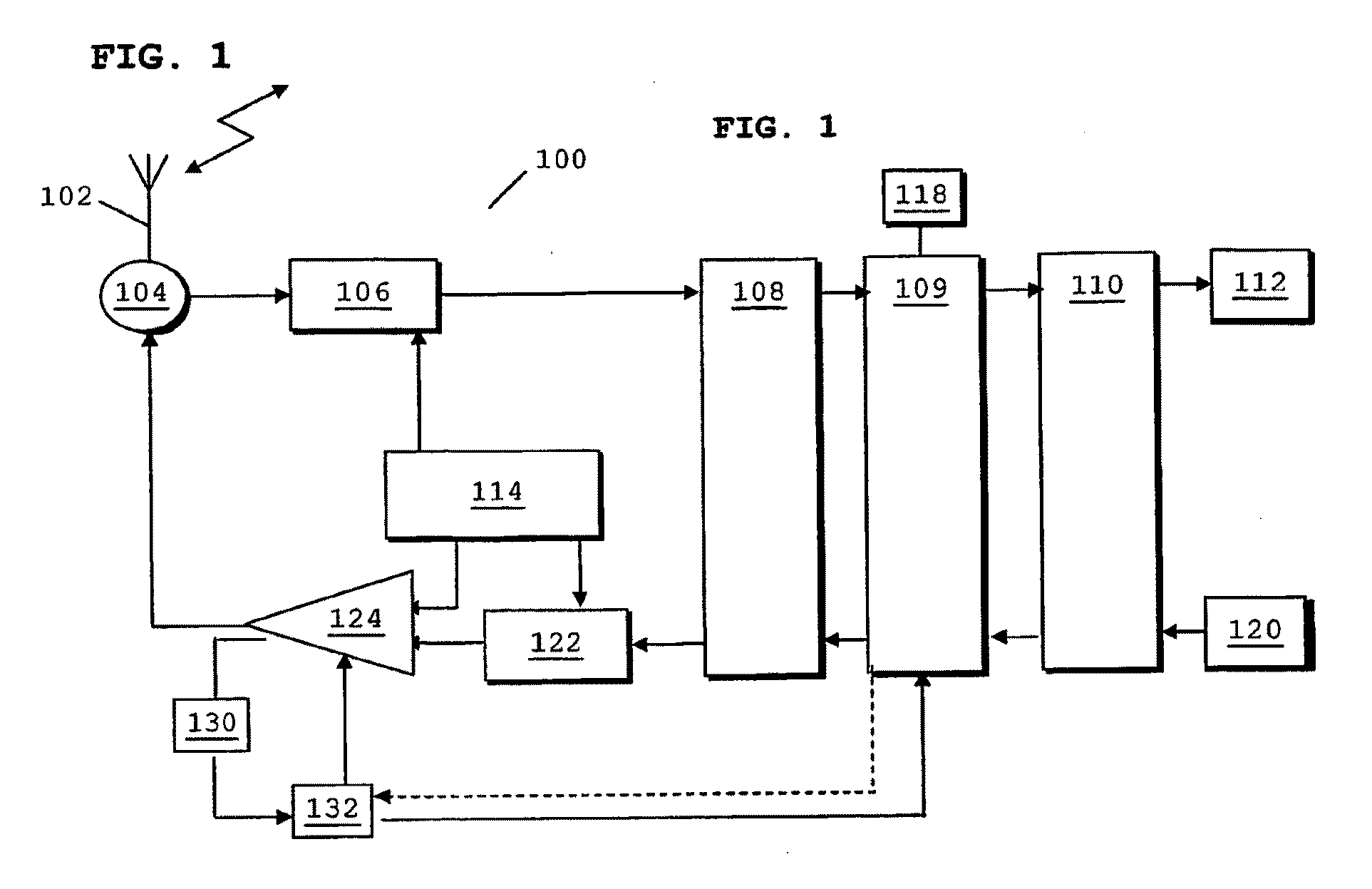
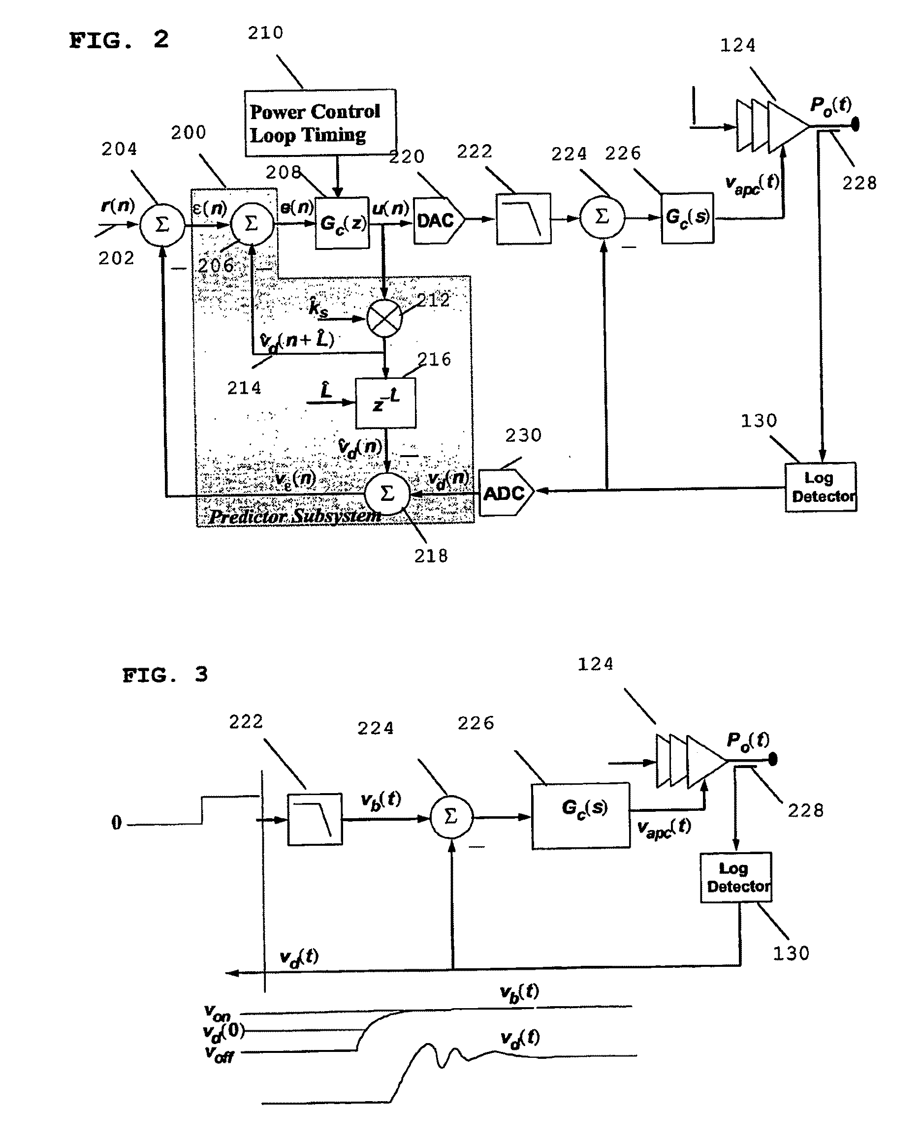
[0032]Some of the aforementioned problems are generally solved by adopting a low-latency, high-gain inner analogue loop comprising a log-detector. The log-detector simplifies the activity detection process; as detection can be performed at a much lower transmit power, for example at −10 dBm for, which allows greater range in the activity detection process.

[0033]In the case of the input power control, with an 8-PSK system, the extended log detector range allows the PA to be activated by switching out step attenuators coupled in the loop, until such time as the detected power first exceeds a desired threshold value.

[0034]A raised cosine (or similar) type of signal is applied to the reference ramp signal, as it has a minimal high frequency transient or switching content. This property is desirable in terms of satisfying the switching or transient spectrum emission specifications of wireless communication standards. The use of a log detector in the feedback path distorts the raised cosi...


PUM


Abstract

A wireless communication unit comprises a transmitter having an analogue feedback power control loop with an input and a power amplifier having a power amplifier output, where the analogue feedback power control loop is arranged to feedback a signal to the input to set an output power level of the transmitter. The wireless communication unit further comprises an outer digital loop operably coupled from the power amplifier output to the transmitter.In this manner, the inner analogue loop is used to linearise a response obtained from the power amplifier and an outer digital loop wherein the outer digital loop controls the inner analogue loop with regard to saturation detection and correction as well as facilitating multi-mode operation of the wireless communication unit.

Description

FIELD OF THE INVENTION[0001]This invention relates to power control in a wireless communication unit. The invention is applicable to, but not limited to, improving the performance of wireless Power Amplifier control loops having a log detector.BACKGROUND OF THE INVENTION[0002]Wireless communication systems, for example cellular telephony or private mobile radio communication systems, typically provide for radio telecommunication links to be arranged between a plurality of base transceiver stations (BTS) and a plurality of subscriber units. An established harmonised cellular radio communication system, providing predominantly speech and short-data communication, is the Global System for Mobile Communications (GSM). GSM is often referred to as 2nd generation cellular technology.[0003]An enhancement to this cellular technology, termed the General Packet Radio System (GPRS), has been developed. GPRS provides packet switched technology on GSM's switched-circuit cellular platform. A yet f...

Claims


Application Information

Patent Timeline
IPC IPC(8): H04B1/04
CPCH03F1/0244H03F1/3252H03F1/3247H03F1/32H03F3/195H03F3/245
Inventor PRATT, PATRICK J.MILYARD, MICHAEL A.SCHWARTZ, DANIEL B.WARDER, PHILIP C.
Owner NORTH STAR INNOVATIONS
Learn More