
System and Method for Azimuth Angle Calibration

a technology of azimuth angle and calibration method, applied in the field of optical metrology, can solve problems such as further complications, and achieve the effect of accurately determining the azimuth angl

Active Publication Date: 2010-01-14
TOKYO ELECTRON LTD
View PDF13 Cites 10 Cited by
  • Summary
  • Abstract
  • Description
  • Claims
  • Application Information

AI Technical Summary

Benefits of technology

[0011]The invention presents an apparatus and method to determine the azimuth angle accurately for an ob

Problems solved by technology

Traditionally the inspection of CDs that are smaller than the wavelength of visible light has been done using large and expensive scanning electron microscopes.
The wafer may also be loaded into the measurement tool at an arbitrary angle creating further complications for instruments that have a preferred measurement orientation with respect to certain wafer features.

Method used


Image

  • System and Method for Azimuth Angle Calibration
  • System and Method for Azimuth Angle Calibration
  • System and Method for Azimuth Angle Calibration

Examples


Embodiment Construction

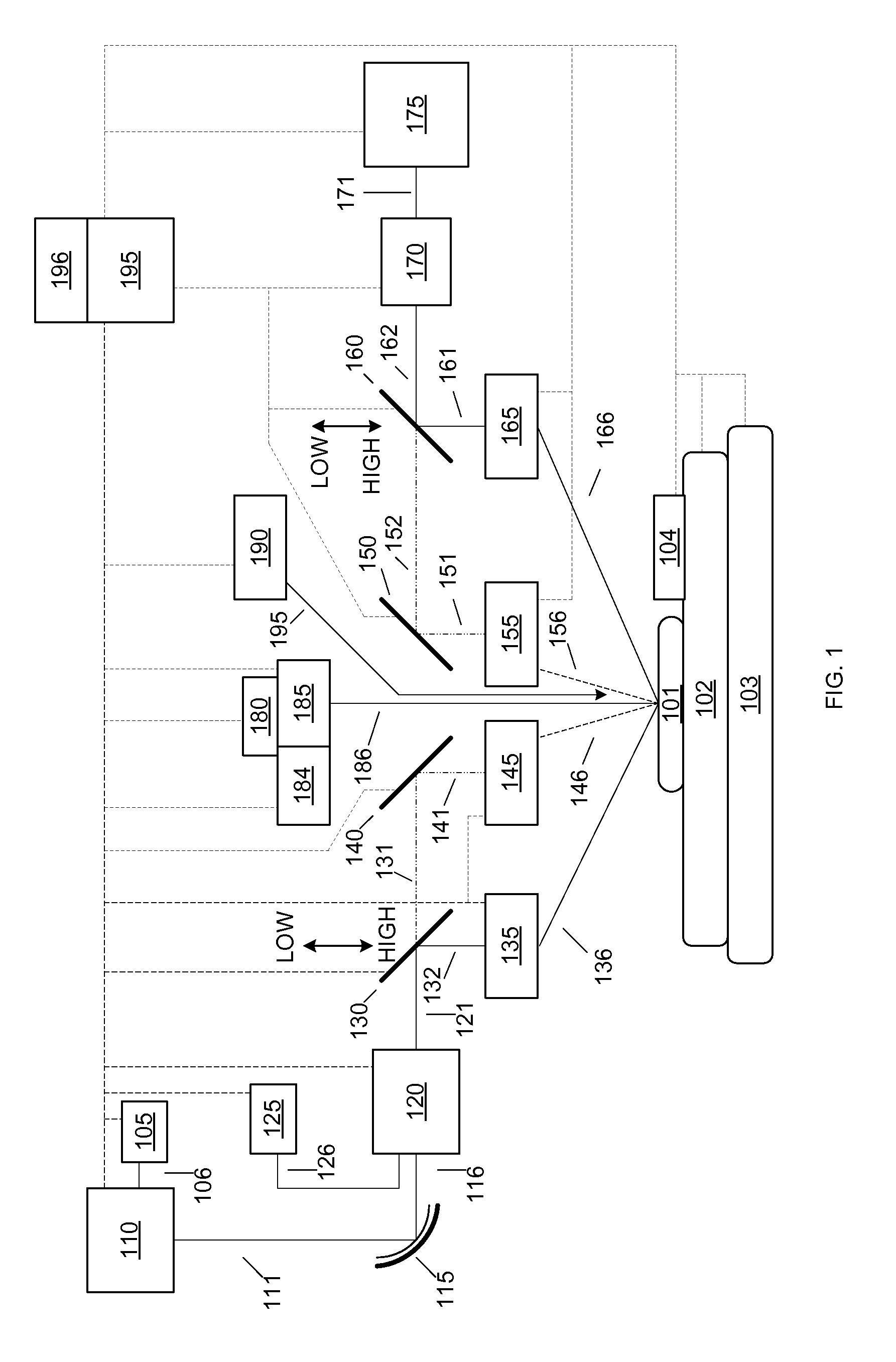
[0020]Reliability, availability, precision, and accuracy are some of the most important performance parameters for semiconductor equipments in a modern fabrication environment. Many semiconductor manufacturers use optical metrology systems for thin-film and CD measurements that include stand-alone tools, and use off-line applications for process monitoring. As the semiconductor roadmap goes to smaller and smaller nodes, the tightened tolerances associated with the smaller structures become more challenging to obtain and verify using semiconductor off-line process control applications. Thus, integrated metrology tools are required to measure the smaller structures made on the wafer. In addition, the measured data from the integrated metrology tools can be used either to optimize the process tools that are being used to create the structures on the wafer, or to adjust the process tool conditions that are being used to further process the wafer. When the metrology tool is integrated as...


PUM


Abstract

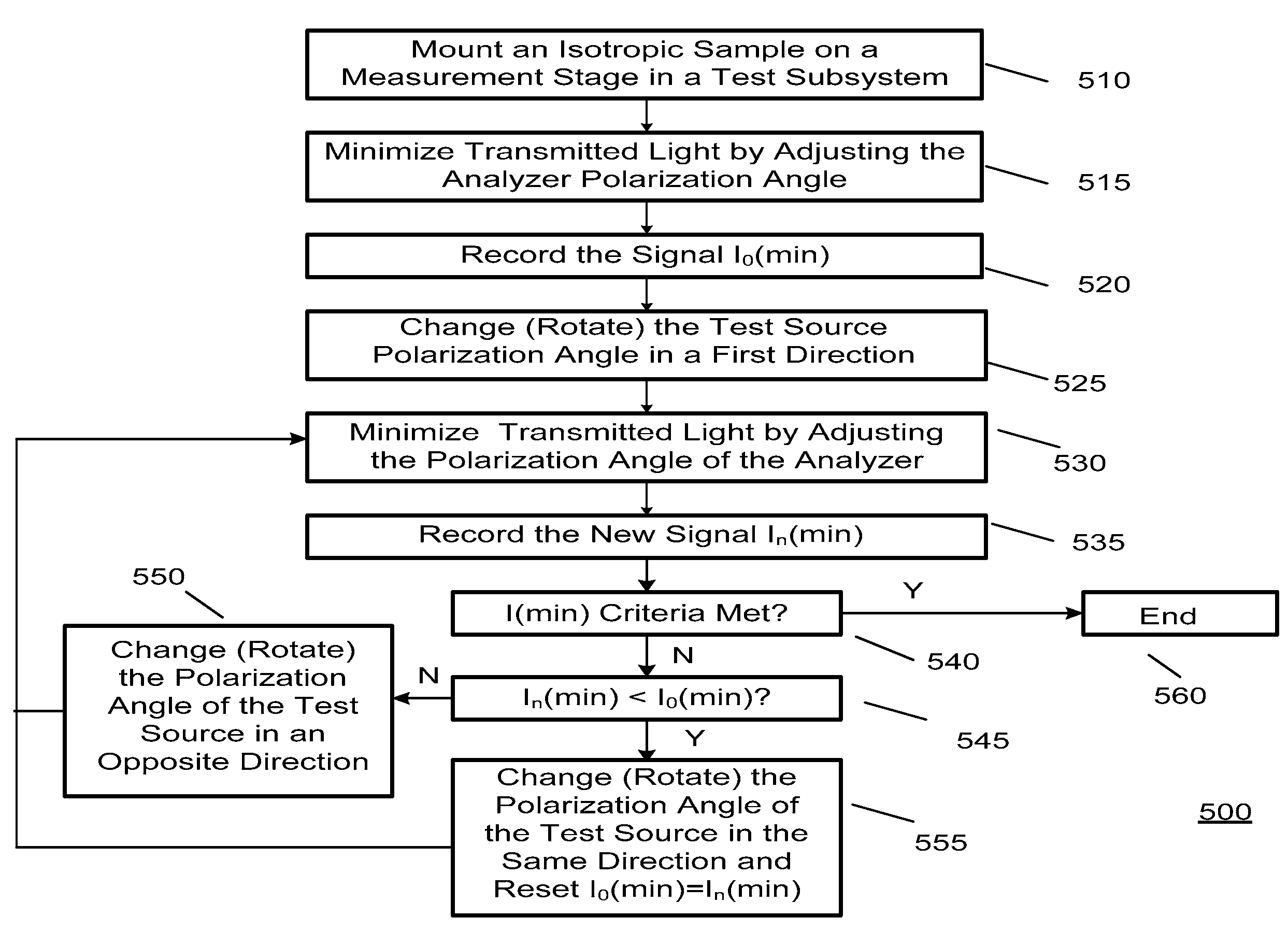
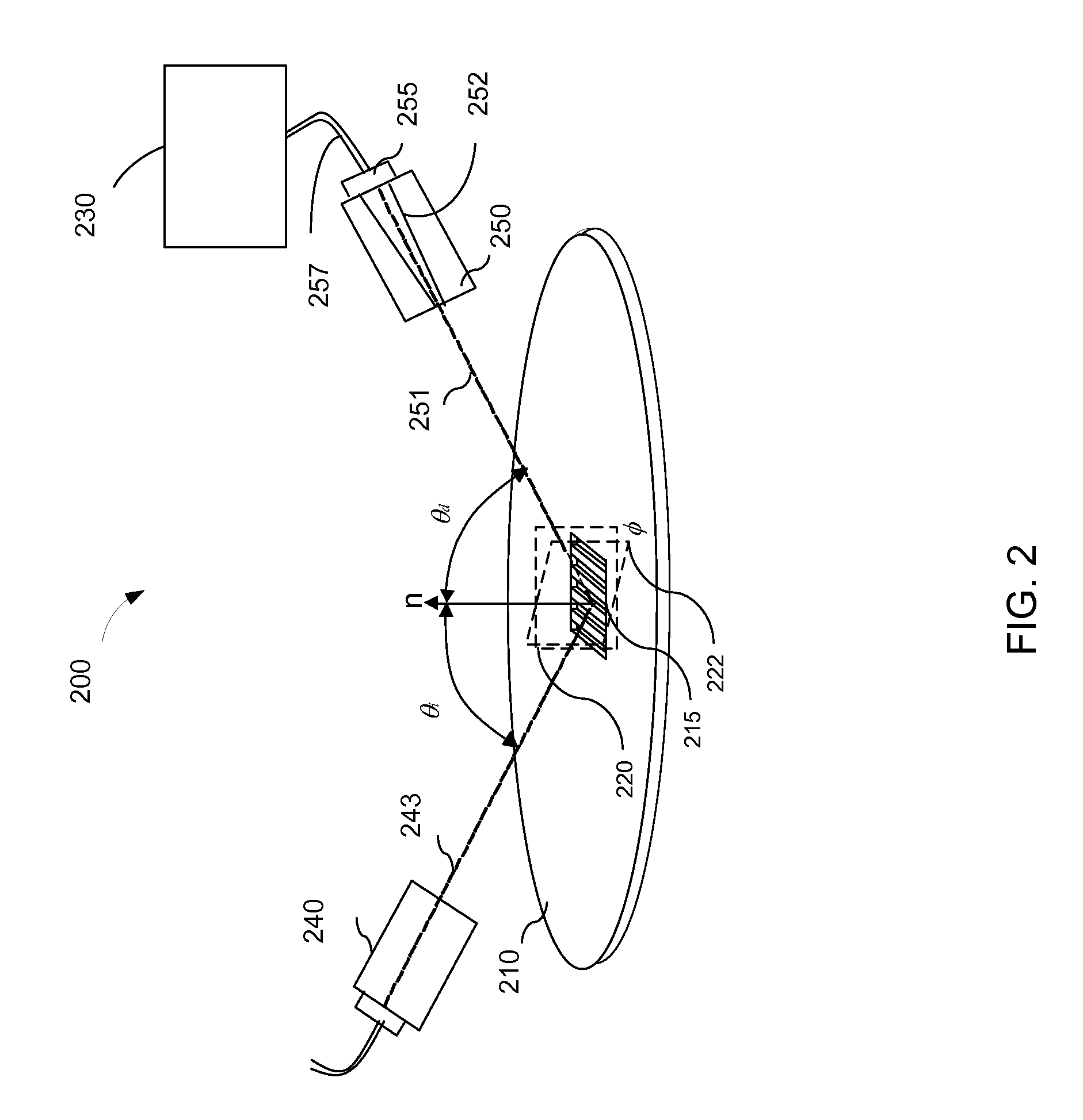
An improved procedure for calibrating the azimuth angle in a metrology module for use in a metrology system that is used for measuring a target on a wafer, and the metrology modules can include oblique Spectroscopic Ellipsometry (SE) and unpolarized or polarized spectroscopic reflectometer devices.

Description

BACKGROUND OF THE INVENTION[0001]1. Field of the Invention[0002]The present invention relates to optical metrology, and more particularly to determining the azimuth angle accurately for an oblique Spectroscopic Ellipsometry (SE) or an unpolarized or polarized spectroscopic reflectometer device.[0003]2. Description of the Related Art[0004]In the manufacture of integrated circuits, very thin lines or holes down to 10 nm or sometimes smaller are patterned into photoresist and then often transferred using an etching process into a layer of material below on a silicon wafer. It is extremely important to inspect and control the width and profile (also known as critical dimensions or CDs) of these lines or holes. Traditionally the inspection of CDs that are smaller than the wavelength of visible light has been done using large and expensive scanning electron microscopes. In many cases, however, manufacturers would like to have measurements immediately after the photoresist has been pattern...

Claims


Application Information

Patent Timeline
IPC IPC(8): G01J4/00G06F19/00
CPCG01N21/211G01N2021/213G01N21/9501
Inventor LI, SHIFANG
Owner TOKYO ELECTRON LTD
Learn More